Magnus Effect experiment problem

In summary, the results of the experiment contradicted the calculations made using the Magnus force formula. The largest cylinder had the least Magnus force, while the smallest cylinder had the largest Magnus force. This could be due to the formula's limitations, or due to the different launch velocities of the different cylinders.
  • #1
DT17
4
0
TL;DR Summary
Ran into a problem regarding a contradiction between my measurements and my calculations, which led to unexpected Magnus Force values.
Hello,

I'm currently doing a school essay on the Magnus Effect, but I'm having a problem regarding a contradiction between my measurements and calculations.
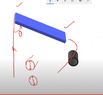
The experiment consists of letting go of rolled A4 paper cylinders on top of a ramp set on a table so that when the cylinder rolls down off the ramp and becomes airborne, it will have a spinning motion and be displaced under the table due to the Magnus effect. My experiment consisted of radius as the independent variable and horizontal displacement under the table as the dependent variable (mass is the same for all). A side view of the experiment looks something like this:
Capture.PNG


When I did the experiment, The cylinder with the largest radius got displaced back the furthest, resulting in a large horizontal displacement, and so it could be implied that the largest cylinder visually had the most noticeable Magnus Effect, and thus, the largest Magnus Force, right? The same applies to the smallest cylinder; the smallest cylinder barely got displaced under the table and looked more like it just fell off due to its higher velocity, thus resulting in very little horizontal deviation and not much of a noticeable Magnus Effect at all. A conclusion for this would be that the larger the radius, the larger the horizontal displacement, and thus, the larger the Magnus Force.

However, when I did the actual Magnus Force calculations, the opposite became true. The cylinder with the largest radius turned out to have the least Magnus Force, while the cylinder with the smallest radius had the largest Magnus Force. How could this happen?

The formula I used for the Magnus force was:

L = ρ⋅v⋅(2πr)^2⋅f⋅l

L is the Magnus Force in N
ρ is the density of the surrounding fluid in kg/m^3
v is the velocity of the projectile in m/s
r is the radius of the cylinder in m
f is the angular velocity of the cylinder in rad/s
l is the length of the cylinder in m

Here are the calculations for the largest cylinder, and smallest cylinder, respectively:

1.2754 ⋅ 1.5009 ⋅ (2π0.045)^2 ⋅ 33.4 ⋅ 0.21 = 1.073 N
1.2754 ⋅ 2.9907 ⋅ (2π0.025)^2 ⋅ 119.6 ⋅ 0.21 = 2.368 N

The only explanation I can think of is that since the radius value changed by such a small proportion, and the angular velocity changed by a much larger proportion, the angular velocity increase outweighed the radius decrease. So my guess is that it happened due to the formula's limitations. My teacher said he kind of ran out of ideas, any help would be greatly appreciated.

Thanks.
 

Attachments

  • 1664387330048.png
    1664387330048.png
    19.2 KB · Views: 82
Physics news on Phys.org
  • #2
Hi and welcome to Physics Forums.
Sounds like a good project.
Interesting that your results turned out to be 'the wrong way round' but that's a common problem with experiments.
I have a question: How do you measure the launch velocities (angular and linear)? You have conflicting requirements here. To show the Magus effect in this way, you chose light cylinders but that means air resistance could make a big difference to the final velocity of a paper cylinder as it rolls down the ramp. You can't just calculate the speeds down the ramp. I understand that you use the same area (i.e. mass) of paper sheet for each cylinder - good move!
 
  • #3
Hello, thanks for your response!

I calculated the velocity of the cylinder by starting a stopwatch the moment it left the ramp and became airborne, and until it struck the ground. I then used Pythagorean's theorem using the horizontal displacement (dependent variable) and table height (height from ground to ramp edge) to find the linear displacement from the edge of the ramp to the landing point, and then calculated the velocity using s/t.
For the angular velocity of the cylinder, I used the formula w= v/r, simply plugging in the velocity and radius.
 
  • #4
DT17 said:
I calculated the velocity of the cylinder by starting a stopwatch the moment it left the ramp and became airborne, and until it struck the ground.
I'm beginning to get the picture now. You are using the distance traveled across the ground in the time it takes to fall? The fact that the cylinders are very light will mean that the time to fall to the ground will be affected by drag as well as by the magus effect. You need an alternative way of measuring or controlling the launch speeds.

If you were to use a heavy smooth metal(?) bar to push the tubes down the slope then they would all be launched at the same speed as the bar. If the bar is very smooth then the tubes will rotate as they should, due to friction on the slope and just slide against the bar. You could find the speed of your bar with the same method as you measure the speeds of the tubes or with a stopwatch, as it rolls down the slope (using SUVAT formulae for constant acceleration) This link shows how to find the acceleration of a round bar / disc; the last few seconds of the video show you the answer if you don't feel like following the whole video. If the bar is longer than the tubes, you can have stops either side to stop the bar and let the tubes fall on their own, leaving the bar behind and you could be sure the launch speed is the same as the bar. A rough slope and a smooth bar means the tubes will all be rotating at the same rate.
If you can perfect that then the Magus effect will (should!) be greater for the smaller diameter tube because it will be spinning faster.
If you are doing this in a school lab then you should be able to find a big metal bar or even a rolling pin (say 50mm diameter) and some clamps to fix some stops at the bottom of the slope. Ask more questions if you need to.
 
  • #5
I believe the motion is very complicated and the velocities and Magnus force are not constants in your experiment. The setup seems good enough to demonstrate that there is a Magnus force but not good enough for actual measurements. Maybe you can change/simplify the experiment to gain more control. You could simply spin (by a wound string or something simple) a cardboard tube on some light armature against a constant air flow from a fan then adjust the speed of the fan, or the rotation of the cylinder and test the force with a little spring scale.
 
  • Like
Likes sophiecentaur
  • #6
bob012345 said:
You could simply spin (by a wound string or something simple)
Maybe a length of piano wire (the sensitive spring), hanging from a motor (drill?) and a hair drier?
But I do like the OP's method because of the built-in contradiction and the possibility of curing it.
 
  • #7
sophiecentaur said:
I'm beginning to get the picture now. You are using the distance traveled across the ground in the time it takes to fall? The fact that the cylinders are very light will mean that the time to fall to the ground will be affected by drag as well as by the magus effect. You need an alternative way of measuring or controlling the launch speeds.

If you were to use a heavy smooth metal(?) bar to push the tubes down the slope then they would all be launched at the same speed as the bar. If the bar is very smooth then the tubes will rotate as they should, due to friction on the slope and just slide against the bar. You could find the speed of your bar with the same method as you measure the speeds of the tubes or with a stopwatch, as it rolls down the slope (using SUVAT formulae for constant acceleration) This link shows how to find the acceleration of a round bar / disc; the last few seconds of the video show you the answer if you don't feel like following the whole video. If the bar is longer than the tubes, you can have stops either side to stop the bar and let the tubes fall on their own, leaving the bar behind and you could be sure the launch speed is the same as the bar. A rough slope and a smooth bar means the tubes will all be rotating at the same rate.
If you can perfect that then the Magus effect will (should!) be greater for the smaller diameter tube because it will be spinning faster.
If you are doing this in a school lab then you should be able to find a big metal bar or even a rolling pin (say 50mm diameter) and some clamps to fix some stops at the bottom of the slope. Ask more questions if you need to.
Yes, I see what you mean. I showed my teacher your comment as well, and he recommended that I should try the experiment again, this time with a rolling pin behind the cylinder so that the initial velocities are equal for all radiuses. He also mentioned that I should use find the velocity using video software (LoggerPro) with 2 phones; 1 positioned perpendicular to the ramp in order to measure the velocity at the edge of the ramp,and the other one recording the trajectory under the table - both phones positioned from the frontal view of the setup. But so would the purpose of this be to have the same linear velocity for all radiuses or the same angular velocity? I'm going to give it a shot anyway and see how it pans out.
 
  • #8
DT17 said:
I showed my teacher your comment as well, and he recommended that I should try the experiment again, this time with a rolling pin behind the cylinder
Your teacher is a 'good lad' in my book. I nearly included the rolling pin idea myself - use what you have!
DT17 said:
find the velocity using video software (LoggerPro)
As I said "use what you have". Data logging is great if it's available.
A video of the falling tubes could be interesting too.
DT17 said:
But so would the purpose of this be to have the same linear velocity for all radiuses or the same angular velocity?
The rolling pin has the same linear velocity with all sizes of tube. You could get equal angular velocities with different tubes by using different lengths of the ramp. The rolling pin method (with data logging) would be easy to set up once you have determined which linear velocities you need for given angular velocities of the tubes. If you plot graphs of the way the (reliable) rolling pin behaves then you 'know' what the tubes are doing without measuring that every time. More results in less overall time.
 
  • #9
sophiecentaur said:
Your teacher is a 'good lad' in my book. I nearly included the rolling pin idea myself - use what you have!

As I said "use what you have". Data logging is great if it's available.
A video of the falling tubes could be interesting too.

The rolling pin has the same linear velocity with all sizes of tube. You could get equal angular velocities with different tubes by using different lengths of the ramp. The rolling pin method (with data logging) would be easy to set up once you have determined which linear velocities you need for given angular velocities of the tubes. If you plot graphs of the way the (reliable) rolling pin behaves then you 'know' what the tubes are doing without measuring that every time. More results in less overall time.

I tried the rolling pin method but it unfortunately didn't work out. The rolling pin's spin stopped the cylinders from spinning and instead just pushed it down the slope. I also tried a roll wrapped in aluminum foil which had considerably less friction than the wooden rolling pin, but it still stopped most of the rotation of the cylinders. It was also quite challenging to get them to launch together simultaneously, stuck to each other. I think the paper cylinders are just too light and fragile for the rolling pin method to work. I did however get good slow-motion video footage; I basically did the same experiment as before, just this time with a camera perpendicular to the slope, and one under the table from behind. Do you think I would be able to do something with the video footage to make up for the fact that I couldn't get the velocities to be the same using the rolling pin?
 
  • #10
DT17 said:
I tried the rolling pin method but it unfortunately didn't work out.
Shame but it must have been because the friction against the ramp was lower than the friction against the rolling pin. The problem with using paper is that, apart from helping to show the Magus effect well, it is subject to other factors that steel (for instance) wouldn't suffer from. If you use a rough ramp and a shiny cylinder then the tubes will stick to the ramp and their speed will be as you wanted.

I can say that, whatever your results and however satisfactory you find this experiment, it will all add to your practical experience in the long run. Behind every expert theoretician there will be a team of equally smart experimenters. :wink:
 

1. What is the Magnus Effect?

The Magnus Effect is a phenomenon in fluid dynamics where a spinning object experiences a force perpendicular to the direction of its motion. It is commonly observed in sports such as soccer and baseball, where the spin of the ball causes it to curve in flight.

2. How does the Magnus Effect affect the trajectory of a spinning object?

The Magnus Effect causes a spinning object to experience a lift or a downward force, depending on the direction of the spin. This results in a curved trajectory instead of a straight line.

3. What are some real-world applications of the Magnus Effect?

The Magnus Effect is used in various sports, such as soccer, baseball, and tennis, to create curved shots. It is also utilized in the design of golf balls and aerodynamic vehicles, such as rockets and missiles.

4. How can the Magnus Effect be demonstrated in an experiment?

An easy way to demonstrate the Magnus Effect is by conducting the classic spinning ball experiment. This involves spinning a ball on a string and observing its curved trajectory when released. Another option is to use a wind tunnel to study the effect of air on a spinning object.

5. What are some factors that can affect the magnitude of the Magnus Effect?

The magnitude of the Magnus Effect can be influenced by several factors, such as the speed and spin rate of the object, the density and viscosity of the fluid, and the shape and surface roughness of the object. Additionally, the angle of attack and the direction of spin relative to the direction of motion can also impact the magnitude of the effect.

Similar threads

Replies
25
Views
2K
  • Other Physics Topics
Replies
7
Views
20K
Replies
7
Views
2K
  • Advanced Physics Homework Help
Replies
1
Views
2K
  • Special and General Relativity
Replies
21
Views
1K
  • Special and General Relativity
2
Replies
66
Views
4K
  • Other Physics Topics
2
Replies
62
Views
8K
  • Introductory Physics Homework Help
Replies
11
Views
668
  • Introductory Physics Homework Help
Replies
1
Views
8K
  • Advanced Physics Homework Help
Replies
3
Views
2K
Back
Top