Discussion Overview
The discussion revolves around the mechanics of levers, specifically focusing on the mechanical advantage related to their size and shape. Participants explore various configurations of levers, questioning how different designs might affect mechanical advantage, and whether certain conditions, like crossing the fulcrum, are necessary for achieving mechanical advantage.
Discussion Character
- Exploratory
- Debate/contested
- Technical explanation
Main Points Raised
- Some participants assert that the mechanical advantage of a first-class lever is consistently 2, regardless of the lever's configuration.
- Others question the necessity of "crossing the fulcrum" and how this might influence mechanical advantage.
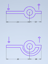
- One participant introduces the idea of modifying the lever by filling it in or drilling holes, prompting discussion about whether these changes affect the lever's function.
- There is a suggestion that the trajectory of force application does not alter the mechanical advantage, as long as the lever remains a rigid body.
- Some participants emphasize the importance of considering work input and output in relation to lever mechanics.
Areas of Agreement / Disagreement
Participants generally agree that the mechanical advantage of a first-class lever can be 2, but there is no consensus on the implications of crossing the fulcrum or the effects of modifications to the lever's structure. Multiple competing views remain regarding the influence of shape and additional features on mechanical advantage.
Contextual Notes
Participants express varying levels of understanding about the physics involved, and there are references to basic principles without thorough exploration of underlying assumptions or definitions. The discussion includes informal language and expressions of uncertainty about the concepts being discussed.
Who May Find This Useful
This discussion may be useful for individuals interested in the mechanics of levers, particularly those exploring the relationship between lever design and mechanical advantage in a practical or theoretical context.