Normal Force Discrepancy for Wedge Vs. Ramp

In summary: Removed?In summary, the normal force between the block and the wall is different in the two examples.
  • #1
engineer5lyfe
6
1
I have seen a few posts on this subject before, but none have really answered my question. For clarity, I will refer to the 1st example as a wedge, and the second as a ramp (although both are of course inclined planes). With both examples that I outline below, we will assume no friction, and a massless wedge/ramp for the sake of simplicity. First, we can begin with the normal force generated from a wedge, for which we know the IMA to be >= 1 provided 45° > theta > 0:

9tCg5.jpg


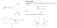
In the case of the wedge, the horizontal force required to maintain equilibrium (F_x) is less than the vertical force applied to the wedge (mg). In this case (static equilibrium), F_y=mg, therefore F_N=mg/cos(theta). Intuitively, this makes sense as we would expect the mechanical advantage of the wedge to be greater than unity for angles < 45°, and therefore F_N should be greater than the input force, F_x.

Now, consider the case in which the block is placed on a ramp. There are two reasonable choices for our reference frames - one in which the x-axis is parallel to the base of the ramp, and one in which the x-axis is parallel to the slope of the ramp. In this case, the choice of reference frame should not affect the description of the normal force. In general, it is more advantageous to choose the latter, which is what we have done below:

cMJZ3.jpg


Shown above is the typical force decomposition that is seen for "ramp" problems, which is similar to the diagram from the wikipedia page on inclined planes, shown below:

DdGME.png


In the above "ramp" case, the normal force is given as F_N=mg*cos(theta). And this is where my quandary lies - for two similar problems, why do we have different results for the normal force? Which is the correct description of the normal force for both cases?

For the case of the wedge, it makes sense that the normal force is greater than the applied horizontal force, because we are essentially trading distance for force to accomplish the same amount of work (if the wedge was allowed to lift the block).

For the case of the ramp, it also makes sense intuitively that the normal force of the block acting on the ramp and vise-versa is less than m*g. For example, we can look at the extremes of the ramp where theta = 90° and theta=0°. For the case in which theta = 0°, the normal force will be equal to m*g, whereas for the case where theta = 90° the normal force is zero, and the block must either be in free fall, or constrained by some friction, if it exist.

I am trying to build both physical intuition, and concrete mathematical evidence of which case is correct, or why the normal forces actually are different for each case. Any help is greatly appreciated, thank you.
 
  • Like
Likes berkeman
Physics news on Phys.org
  • #2
The force from the wall is not directed in your chosen x direction in the second example but you assume that it is.
 
  • #3
Orodruin said:
The force from the wall is not directed in your chosen x direction in the second example but you assume that it is.
F_x for the second case would be a component of the normal force between the wall and the block, correct? The way that I see it, the sum of the components, F_x and F_y for the second example should equal the normal force on between the block and the wall. Perhaps I am misunderstanding, could you please elaborate?
 
  • #4
engineer5lyfe said:
F_x for the second case would be a component of the normal force between the wall and the block, correct? The way that I see it, the sum of the components, F_x and F_y for the second example should equal the normal force on between the block and the wall. Perhaps I am misunderstanding, could you please elaborate?
Incorrect. You can split all the forces into their components, but the force triangle is made by the normal force, the weight, and the horizontal force from the wall regardless of the coordinates you pick.
 
  • #5
Orodruin said:
Incorrect. You can split all the forces into their components, but the force triangle is made by the normal force, the weight, and the horizontal force from the wall regardless of the coordinates you pick.
I think I understand - thank you for the clarification. I've included an updated diagram below to check my understanding. So in both cases, F_N=mg/cos(theta)? Why then is F_N=mg*cos(theta) if the wall constraint is removed?

Capture.JPG
 
  • #6
engineer5lyfe said:
I think I understand - thank you for the clarification. I've included an updated diagram below to check my understanding. So in both cases, F_N=mg/cos(theta)? Why then is F_N=mg*cos(theta) if the wall constraint is removed?

View attachment 313980
After posting this reply, I now see that F_N is reduced when the wall constraint is removed, because no horizontal force exists, therefore the normal force only has to react to mg, and therefore F_N=mg*cos(theta).
 
  • #7
engineer5lyfe said:
After posting this reply, I now see that F_N is reduced when the wall constraint is removed, because no horizontal force exists, therefore the normal force only has to react to mg, and therefore F_N=mg*cos(theta).
Right, if you add a horizontal force, that force will have a component in the normal direction.
 
  • Like
Likes engineer5lyfe
  • #8
I have decided to add an addendum to this post in case others come across it - hopefully it will help build intuition and understanding as to why the normal force changes for different situations.

The first example is a "wedge", however the input force required to maintain static equilibrium could just as well be a reaction force if the wedge were grounded.

1662855028092.png

1662855088762.png


Per the above sum of forces, we can see that the normal force must react against the wall reaction/input force and the weight of the object resting on the ramp. Therefore, it must be the largest force in the system to maintain static equilibrium. We can also see that the vector loop is invariant with respect to coordinate system choice - the components of the vectors can be determined relative to any coordinate system, and the magnitude of the forces will not change.

We can now consider a ramp, this time with friction as I feel that it is an easier system to grasp before moving on to a dynamic system.
1662855322663.png

1662855361963.png

Note that in this case, the normal force is not the largest force. It only has to react to the weight component that is orthogonal to the sloped face. The friction force (which has no component orthogonal to the slope face) handles the reaction to the rest of the weight to maintain static equilibrium.

For the final case, we can analyze the situation above without the friction. With friction eliminated, we know from intuition that the block will slide down the ramp. However, in most examples the forces acting on the ramp are omitted from the analysis, because they are generally not of any interest. But in this case, I think it is worthwhile to show them.
1662856489136.png


1662857538414.png


I previously said that it was worthwhile to show the reaction forces on the ramp. This is because our result is interesting - for the ramp, the normal force is the greatest as it must "react" to the reaction forces caused by the fixed conditions of the ramp. However, for the block, we see the typical diagram that is shown, in which the normal force is less than the weight. Intuitively, this makes sense as only the portion of the weight normal to the slope face has to be reacted, while the "rest" of the force (that is, the component parallel to the slope face) is "used" to change the momentum of the block.

I hope this addendum is informative for those that had a similar question to the one initially posed. My issue was that I was taking shortcuts in not actually drawing out the forces and looking at the vector loops - I was trying to break everything down into components first.
 

Attachments

  • 1662856507200.png
    1662856507200.png
    11.6 KB · Views: 51
Last edited:
  • #9
Welcome!
Very nice drawings!

The equations of the second case show a Fin that does not exist.

The drawings and the equations of the third case show a force of friction between both blocks that does not exist.
 
  • #10
Lnewqban said:
Welcome!
Very nice drawings!

The equations of the second case show a Fin that does not exist.

The drawings and the equations of the third case show a force of friction between both blocks that does not exist.
For the first case (which I assume you are referring to, as it is the only one with F_in), F_in is simply a force that is required to maintain static equilibrium since no friction is present in the system. It "exists" because it is prescribed by the problem, such that there is static equilibrium.

For the third case, the force that you are referencing is F_fict (fictitious force - arising from the implementation of d'Alembert's principle), but I can see how it could be mistaken as a friction force. If you look at the equations of motion, you will see that no friction force is present.
 

1. What is the Normal Force Discrepancy for Wedge Vs. Ramp?

The Normal Force Discrepancy for Wedge Vs. Ramp refers to the difference in the normal force experienced by an object placed on a wedge compared to the normal force experienced by the same object placed on a ramp at the same angle. This discrepancy occurs due to the difference in the geometry of the two surfaces.

2. Why does the Normal Force Discrepancy occur?

The Normal Force Discrepancy occurs because the wedge has a smaller surface area in contact with the object compared to the ramp. This results in a larger normal force on the ramp as it is spread out over a larger area, while the same force is concentrated on a smaller area on the wedge.

3. How does the Normal Force Discrepancy affect the motion of the object?

The Normal Force Discrepancy does not affect the motion of the object as it is a static force. However, it does affect the stability of the object on the surface. The larger normal force on the ramp provides more stability compared to the smaller normal force on the wedge.

4. Can the Normal Force Discrepancy be eliminated?

No, the Normal Force Discrepancy cannot be eliminated as it is a result of the geometry of the surfaces. However, it can be minimized by increasing the angle of the wedge or ramp, which increases the surface area in contact with the object and reduces the discrepancy.

5. Are there any real-life applications of the Normal Force Discrepancy for Wedge Vs. Ramp?

Yes, the Normal Force Discrepancy has practical applications in various fields such as engineering, physics, and construction. It is important to consider this discrepancy when designing structures or machines that involve wedges or ramps to ensure stability and safety.

Similar threads

Replies
13
Views
5K
  • Introductory Physics Homework Help
Replies
12
Views
2K
  • Introductory Physics Homework Help
Replies
10
Views
776
Replies
20
Views
2K
  • Introductory Physics Homework Help
Replies
4
Views
893
  • Introductory Physics Homework Help
Replies
5
Views
1K
  • Introductory Physics Homework Help
2
Replies
41
Views
2K
Replies
3
Views
2K
Back
Top