Troubleshooting MCNP k_eff for Space Reactor Core: Tips and Tricks"

  • Thread starter Thread starter AlexFi
  • Start date Start date
  • Tags Tags
    Mcnp
AI Thread Summary
The discussion focuses on troubleshooting an MCNP model of a space reactor core, where the user initially obtained a k_eff value of 1.4, significantly higher than the expected 1.003. Key issues identified include incorrect volume fractions for UO2 and graphite, as well as geometry misconfigurations, particularly with the lattice and void cell definitions. Adjustments to the atomic ratios and material densities were suggested, with a recommended graphite density of around 1.77 g/cm³. The conversation emphasizes the importance of accurately defining the reactor's geometry and material properties to achieve a realistic k_eff value, which was ultimately brought down to 1.176 after several corrections.
AlexFi
Messages
19
Reaction score
5
TL;DR Summary
Tried to model a reactor, got k_eff of 1.4 instead of reference 1.003
Hello!
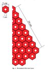
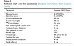
I tried modeling a space reactor core with MCNP. I'm pretty sure the geometry and material properties are correct.
Got k_eff of 1.4, much higher than 1.003 from the reference.
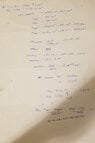
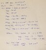
Could anyone spot the mistake in my code? I couldn't figure out anything else
 

Attachments

  • Opus_fill.txt
    Opus_fill.txt
    655 bytes · Views: 182
  • Untitled(1).jpg
    Untitled(1).jpg
    24.3 KB · Views: 157
  • Untitled.jpg
    Untitled.jpg
    23.9 KB · Views: 153
Engineering news on Phys.org
If the core is supposed to have an excess reactivity of 3000pcm (I googled), isn't that a keff of around 1.03? Presumably that is with the reflectors.

The fuel is graphite with 45%vol UO2 BISO particles, not solid UO2.

You have cookie cut the core a bit weird. You may need to abandon the segment method and define the lattice.
 
  • Informative
  • Like
Likes berkeman and Astronuc
Alex A said:
If the core is supposed to have an excess reactivity of 3000pcm (I googled), isn't that a keff of around 1.03? Presumably that is with the reflectors.

The fuel is graphite with 45%vol UO2 BISO particles, not solid UO2.

You have cookie cut the core a bit weird. You may need to abandon the segment method and define the lattice.
Thanks for spotting that mistake! Adding 45% vol graphite increased k_eff to 1.57 though..
 

Attachments

You've given it 45% carbon, not 45% UO2. You've done it by atomic fraction, not volume. Probably easiest to work it out and then enter mass fractions as negative numbers. The other thing, is that the density of the fuel drops.
 
k+eff is 1.24 now
Anything else I need to change?
 

Attachments

  • Opus_fill.txt
    Opus_fill.txt
    671 bytes · Views: 170
  • molfrac calc.jpg
    molfrac calc.jpg
    17.8 KB · Views: 157
There is a typo in cell 99, it should be 500 and -501.

Your graphite density (2.26g/cc) is right for single crystal graphite, but, and I would welcome input here from experienced hands, I think reactor graphite is probably 1.8g/cc or less. I think I went with 1.77, the mid point for what google says is the pressed, sintered stuff I'm thinking of.

74c needs extending to other elements. It's a bit hot, but it's probably the closest.

That brings us to the cookie cutter issue. You've defined a lattice and then cut a cylinder through it. I think you will need to define which rods are present. Without doing this I'm down to around 1.07. I don't know if will make it worse, I don't see any total mass numbers to make a guess.

So yeah, sorry, but a fair bit left to do if you want it accurate.
 
I redid the atomic ratio & density calculation with graphite density of 1.77 g/cm^3 and I can only get k_eff down to 1.176
I cannot put .74c in the graphite because if I do so, I get 'cross section table missing' error
Also how should I define cell 99?
 

Attachments

  • molfrac calc2.jpg
    molfrac calc2.jpg
    32.7 KB · Views: 146
  • Opus_fill.txt
    Opus_fill.txt
    673 bytes · Views: 155
You've written 1:4.392 molar ratio UO2 to C. That seems about right. The next line though, you've gone 0.31 U235 ... 4.392 C. Something went wrong. I agree with the density.

The void cell should be everything that isn't an active cell and it should completely surround the experiment. You have no limits in z (your core does, your experiment doesn't), which I don't like but for now MCNP seems happy.

Code:
99 0 2:-500:501 imp:n=0

Usually it's the union of all areas that are no part of the problem and the outside. Your experiment is a slice of cake shape where the straight edges reflect - this produces a simulation of a complete reactor core with symmetry. So your void cell is the union of everything the wrong side of 500, everything the wrong side of 501 and everything outside of 2.

In your lattice example you tried -9:-7:-5:-3:-1:501, -9 is inside macro body surface 9. -7 is inside macro body surface 7. You can't easily fix this, the use of macro bodies placed inside the core is going to make defining the missing volume complicated.

My thoughts are to make a universe of cooling tube surrounded by core rod material, specify those in a hexagonal lattice which does the hexagonal cookie cutting, then surrounded by a cylinder. Your core then has the right shape, the cylinder isn't cutting into the actual rods, and volumes like the void become easy to define and it can be easily extended to cases with rods of mixed lower enrichment.
 
Firstly I was wrong that your experiment is not limited in z, surface 2 is a macro body and it does do this. Do watch out if you ever need to add a reflector!

Almost all the information I can find on OPUS comes from "The challenges of gas-cooled reactor technology for space propulsion and the development of the JANUS space reactor concept" by Aiden Peakman and Robert Gregg. I can't find copies of the Raepsaet and Pascal, or Lokhov papers that are the primary sources for the information on the core. The core diagram we do have contains a measurement of 24cm, and I question why it isn't 21cm (3x7) or there isn't an extra layer of rods around, and I can't make the number of fuel rods add up. The 235 rods, which is the design the diagram seems to indicate, without reflector ought to be subcritical and it isn't (keff=1.07).

So I made a few tweaks to the input file. I kept the segment design. I flipped surface 501 around so it aligned with lattice numbering better. I'm using my rough numbers for material values which may be very rough and lastly I may have made any number of mistakes.

Major edit - I did make mistakes, I messed up the rod count on the version I uploaded by a lot. I think it's right now.
 

Attachments

Last edited:
  • #10
Alex A
Thank you so much
I haven't tested your code yet, but here's the Lokhov paper. I just got it today
 

Attachments

  • #11
AlexFi said:
Alex A
Thank you so much
I haven't tested your code yet, but here's the Lokhov paper. I just got it today
I never learned how to use the lattice-universe thing properly
How should I modify the code if I want to change the material of the elements in the perimeter of the core from helium to graphite?
 
  • #12
Untested, and it will just make the overcritical core worse :) Change the first cell 2 line to,
Code:
2 3 -1.77 -1 lat=2 u=1 fill=0:6 -11:0 0:0
So all universe 1 entries in the table will then be mat 3, graphite, but they only show on the outer edge so it should be fine.

The paper seems to indicate they used the 1/12 simulation as a coupled thermodynamic/neutronic solution for thermal tests but they don't give a keff. The keffs they give are for the core in four quarters design with more rods (4x63 total) and reflectors around the edge, above and below. There is a lot more space in the middle of the core with no fissile material so that has a good chance of being under critical like it's supposed to be.
 
Back
Top