Tazzlest
- 1
- 0
Hi everyone,
I have this assignment which involves drawing this circuit schematic of a diagram that is put together on a bread board. Only thing is, however, that I do not understand how a breadboard works, therefore it makes this task really difficult. Can someone help me explain how this must be drawn? Here is an image of the diagram:
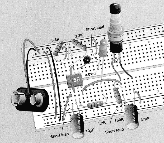
Apparently there is a 555 IC Timer as well but I don't even know how to approach drawing that in a circuit schematic.
Additional notes:
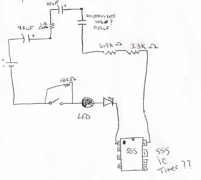
Here is my, what I assume is completely wrong, attempt:
I have this assignment which involves drawing this circuit schematic of a diagram that is put together on a bread board. Only thing is, however, that I do not understand how a breadboard works, therefore it makes this task really difficult. Can someone help me explain how this must be drawn? Here is an image of the diagram:
Apparently there is a 555 IC Timer as well but I don't even know how to approach drawing that in a circuit schematic.
Additional notes:
The button used is a momentary pushbutton switch.
The two capacitors at the bottom of the circuit are polarized capacitors and the capacitor labeled with “103” is non-polarized.
Here is my, what I assume is completely wrong, attempt: