Vincci
- 1
- 0
I need help in creating this circuit. It was given as my final year project for my foundation in electrical and electronic engineering by my lecturer. Every component seems to work perfectly fine especially when it is tested in sub circuits. The problem arises when I try to simulate the whole circuit the LEDs which each represent a number from one to sixteen just continuously switch on and off. I have attached the circuit diagram from which I am to recreate the circuit from. The transformer, 230 A.C power source, IC6 , C3, C4, D17 and D18 are not going to be used as a powered bread board will be used as the power source.
Ps: I have separated the circuit into three subcircuits which the first one comprises of the 555 and power supply, the second comprises of the 74161 and 7400 and the third comprises of the 74157 and 75154. And all of these circuits work perfectly fine when tested separately. But when I try to simulate the full circuit the LEDs will not light up as they are supposed to.

F
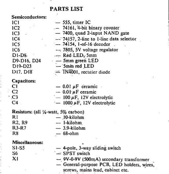
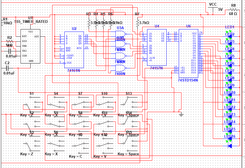
Ps: I have separated the circuit into three subcircuits which the first one comprises of the 555 and power supply, the second comprises of the 74161 and 7400 and the third comprises of the 74157 and 75154. And all of these circuits work perfectly fine when tested separately. But when I try to simulate the full circuit the LEDs will not light up as they are supposed to.
F