Opamp as amplifier: Not getting the desired gain

Join the discussion
Ask a follow-up here, or get your own question answered by working scientists, mathematicians and engineers — people, not an autocomplete.
Real named experts · corrections over time · the nuance an AI answer skips
9 replies · 4K views
Nikhil N
Messages
80
Reaction score
2
I want to amplify my input AC,50Hz to 30 times. I just started to test the basic inverting amplifier, with R2=4.7K and R1=1K. I varied the Vpp from 1 to 5 and I observed, I am not getting the gain of 4.7. Why this is happening ? One more doubt that I have is I used 12V Vcc, so if the input is 5V, is it possible to amplify it to 5*4.7 = 23.5 ? This doubt is because we are only providing 12V to IC, then how it can generate more than 12V?
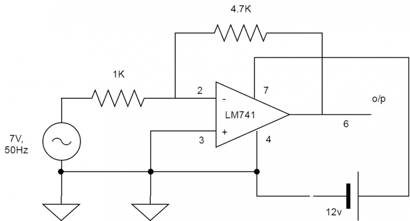
op_amp.png


The observations I got is as :
tbl.PNG
 
Engineering news on Phys.org
The usual arrangement is to supply the op-amp with a symmetrical power supply, e.g., +12V and –12V, with the power supply midpoint used as ground. Your circuit shows a single supply, this arrangement is not suitable for your amplifier.

You can't have an output level exceeding the supply rail, so for testing purposes you need to reduce the amplitude of the input to verify the gain. Were you monitoring your op-amp's output using an oscilloscope, you would see that the output is a very distorted waveform, nothing like its sinusoidal input, so you could not even say this is "amplifying".

Application notes published by semiconductor manufacturers are an invaluable source of information to the circuit designer. Refer to one for the 741, you can find it online. Download it; commit it to memory. :smile:
 
  • Like
Likes   Reactions: AlexCaledin
Nikhil N said:
This doubt is because we are only providing 12V to IC, then how it can generate more than 12V?
It cannot.
You must design to the worst case limits. The 741 op-amp is specified at VS = ±15 V as having;
Input voltage range ±12 V. So the inputs must be 3 volts inside the power supplies.
Output voltage swing ±10 V. So the outputs won't always go within 5V of the supplies.
Don't expect output current of more than 10mA, it will limit output short circuit output to about 25 mA.
 
NascentOxygen said:
The usual arrangement is to supply the op-amp with a symmetrical power supply, e.g., +12V and –12V, with the power supply midpoint used as ground. Your circuit shows a single supply, this arrangement is not suitable for your amplifier.

You can't have an output level exceeding the supply rail, so for testing purposes you need to reduce the amplitude of the input to verify the gain. Were you monitoring your op-amp's output using an oscilloscope, you would see that the output is a very distorted waveform, nothing like its sinusoidal input, so you could not even say this is "amplifying".

Application notes published by semiconductor manufacturers are an invaluable source of information to the circuit designer. Refer to one for the 741, you can find it online. Download it; commit it to memory. :smile:
IMG_20170214_091116.jpg

I have a voltage supply of this kind. But when I measured voltage between +ve and GND(Middle) using my multi meter I am not getting +12V, same the case with -ve and GND. But I am getting +12V between +ve and -ve terminals. Can you tell me how can I connect +12V and -12V from this supply.
 
Nikhil N said:
View attachment 113255
I have a voltage supply of this kind. But when I measured voltage between +ve and GND(Middle) using my multi meter I am not getting +12V, same the case with -ve and GND. But I am getting +12V between +ve and -ve terminals. Can you tell me how can I connect +12V and -12V from this supply.
It is likely you cannot.
 
It is a single adjustable supply that can produce up to 32 volts, so you can set it to produce 24 volts output. Use two equal value resistors, maybe 100 ohm, rated at 2 watt each, to split the 24 volts, connect the junction to the ground of your input signal and the Earth of the supply. Don't forget to use bypass capacitors at the op-amp, (0u1F ceramic), and on the (+, gnd, – ) of the power supply.

An LM741 op-amp will not be able to drive a load that is below about 500 ohms.
 
  • Like
Likes   Reactions: Averagesupernova
Baluncore said:
It is a single adjustable supply that can produce up to 32 volts, so you can set it to produce 24 volts output. Use two equal value resistors, maybe 100 ohm, rated at 2 watt each, to split the 24 volts, connect the junction to the ground of your input signal and the Earth of the supply. Don't forget to use bypass capacitors at the op-amp, (0u1F ceramic), and on the (+, gnd, – ) of the power supply.

An LM741 op-amp will not be able to drive a load that is below about 500 ohms.
op_amp.png


Is this circuit correct ? This will make both +12V and -12V at the divider circuit, so I hope this is what you have suggested.
 
Nikhil N said:
Is this circuit correct ?
Almost. But remove the short circuit from between pins 3 and 4.
Change feedback gain setting resistors from 1k0:4k7 to 10k:47k to reduce load on split ground.
Note that: Gain of 4.7 * 7V input = 28V, which is outside the supply of amplifier.
But if the input is 7VAC = 7Vrms = 7 * √2 = ± 10 V peak. Any gain will take the output to the power rails.
