Parallel Plate Fields: Questions & Answers

Join the discussion
Ask a follow-up here, or get your own question answered by working scientists, mathematicians and engineers — people, not an autocomplete.
Real named experts · corrections over time · the nuance an AI answer skips
6 replies · 2K views
aspodkfpo
Messages
148
Reaction score
5
Homework Statement:: n/a
Relevant Equations:: n/a
1597754102234.png


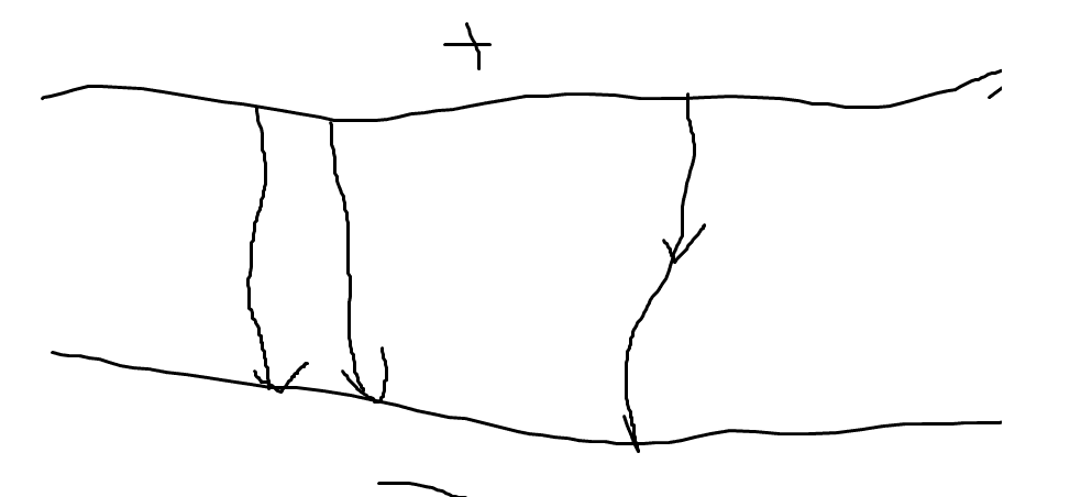
Sorry for the wonky mouse sketching. Teacher said that arrows must touch the plate at the other end. Is there actually such a thing or is this just preference? I thought convention was for arrow to be in the middle of the line.
 
Physics news on Phys.org
As far as I am aware there is no such convention for field lines. Field lines are just curves tangent to the vector field, and don't even necessarily require arrows (although they're pretty helpful to insert).

But if you are instead sketching a vector field, i.e. drawing an arrow at every point in space, then you need to make clear whether the arrow represents the field at the point of the tip, tail or middle of the arrow. This is important, since the electric field at each point in space is a bound vector.
 
Last edited by a moderator:
Yeah, looks like it's done both ways.

https://buphy.bu.edu/~duffy/PY106/cap1.GIF

1597756043570.png


https://lh3.googleusercontent.com/proxy/ot9IExHXVFIK7Fo9lRFv_gPHTkJH0XJP5j8XpDOEuPsyC3W-J3dWesF4mPw-No-pfHh109Hy9XSAIwkx4FyfaxFyyFO6ZQYWIOT6qxDg79NCnoNBjcOKGbL1X5A5tIvKDA

1597756081745.png


I usually put the arrowhead at the end for the E-field in a capacitor, but in the middle for the magnetic field around a magnetic dipole, for example.
 
  • Like
Likes   Reactions: vanhees71
berkeman said:
Yeah, looks like it's done both ways.

https://buphy.bu.edu/~duffy/PY106/cap1.GIF

View attachment 267917

https://lh3.googleusercontent.com/proxy/ot9IExHXVFIK7Fo9lRFv_gPHTkJH0XJP5j8XpDOEuPsyC3W-J3dWesF4mPw-No-pfHh109Hy9XSAIwkx4FyfaxFyyFO6ZQYWIOT6qxDg79NCnoNBjcOKGbL1X5A5tIvKDA

View attachment 267918

I usually put the arrowhead at the end for the E-field in a capacitor, but in the middle for the magnetic field around a magnetic dipole, for example.
For the red diagram a) that you whipped up, it shows the field outside of the plates. Is that meant to be drawn?
 
aspodkfpo said:
For the red diagram a) that you whipped up, it shows the field outside of the plates. Is that meant to be drawn?
LOL, I "whipped it up" by doing a Google Images search. I find that to be a very helpful way to get a quick look at possible solutions and visulaizations. I think my search phrase at Google Images was something like Electric Field in a Capacitor or similar.

As far as the E-field outside of the volume of the capacitor, that is called the "fringe field", and is usually only relevant and considered if the spacing between the plates is on the same order as the size of the plates. When the plate separation << than the linear dimensions of the plates, the contribution to the capacitance from the fringe field is usually negligible. Does that make sense?
 
  • Like
Likes   Reactions: etotheipi and aspodkfpo
What are the arrows representing? Field vectors or field lines? In the latter case, the important point is that the lines should touch the plates (so you don't have field lines appearing out of nowhere) not where the arrowhead is drawn. It seems possible that this is what your teacher means.
 
Last edited:
The field lines must end on the plates, because that's where charges are sitting. Field lines start (positive charge) and end (negative charge) at the sources according to ##\vec{\nabla} \cdot \vec{E}=\rho/\epsilon_0##. That's also why magnetic field lines (with ##\vec{B}## as the magnetic field!) must never have a beginning and an end, i.e., they always form closed loops (sometimes in idealized situations like an infinite coil at infinity).
 
  • Like
Likes   Reactions: Ibix and etotheipi