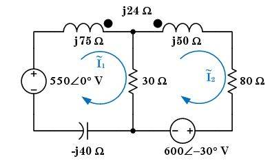
Phasor Mesh Current-what am I doing wrong?

  • Thread starter Thread starter teh_dude
  • Start date Start date
  • Tags Tags
    Mesh Phasor
Join the discussion
Ask a follow-up here, or get your own question answered by working scientists, mathematicians and engineers — people, not an autocomplete.
Real named experts · corrections over time · the nuance an AI answer skips
6 replies · 4K views
teh_dude
Messages
11
Reaction score
0
Phasor Mesh Current--what am I doing wrong??

Homework Statement


Circuit diagram:
meshphasor.jpg

Calculate the phasor mesh currents, I1 and I2.

Homework Equations


KVL/Mesh Current analysis with phasors/complex numbers.

The Attempt at a Solution


Mesh 1: (-550@0deg) + j75(I1) + 30(I1 - I2) - j40(I1) - j24(I2) = 0

Mesh 2: (600@-30deg) + 30(I2 - I1) + j50(I2) + 80(I2) - j24(I1) = 0

(30 + j35)I1 - (30 + j24)I2 = 550
-(30 + j24)I1 + (110 + j50)I2 = (-600@-30deg)

I got:

I1 = (9.45503221553 @ -38.8333374187 degrees) A

I2 = (2.79176352576 @ 93.1719060416 degrees) A

This problem was even demonstrated in class. Yet the homework site keeps telling me I'm wrong. I don't see where I've made a mistake...?
 
Physics news on Phys.org


Maybe check that the signs of the mutual inductance terms respect the dot notation and choice of loop current directions?


rude man said:
How did you incorporate the 600V at -30 degrees in your equations? You didn't show us that, so we can't find your mistake for you, if there is one.

Mesh 2: (600@-30deg) + 30(I2 - I1) + j50(I2) + 80(I2) - j24(I1) = 0

How else can I demonstrate? It's there.

If you mean how did I mix polar notation with rectangular notation, I punched it all into the TI-89, in which the modes were set to degree, polar, and approximate.

Otherwise, I don't know what you're getting at.
 
Last edited:


gneill said:
Maybe check that the signs of the mutual inductance terms respect the dot notation and choice of loop current directions?

I don't entirely understand how to deal with the polarity marks, but I've tried switching plus and minus for the j24Ω term. It's my understanding that they should both be -j24Ω, multiplied by I1 or I2 respectively, but I've tried both minus, both plus, one minus, one plus, the other way around, and none of the answers are correct.


teh_dude said:
I don't entirely understand how to deal with the polarity marks, but I've tried switching plus and minus for the j24Ω term. It's my understanding that they should both be -j24Ω, multiplied by I1 or I2 respectively, but I've tried both minus, both plus, one minus, one plus, the other way around, and none of the answers are correct.

I've taken a closer look at your circuit and I believe that you have them correctly oriented. Sorry for the bother.

The idea is that a positively increasing current flowing into one coil at its dot produces a positive polarity of induced voltage at the dot of the second coil. So you have to be attentive as to whether a positive increase in the mesh current will create a positive increase in the current flowing into the coil dot, or whether it will in fact cause a decrease.

attachment.php?attachmentid=41401&stc=1&d=1322725464.jpg
 

Attachments

  • Fig1.jpg
    Fig1.jpg
    7.5 KB · Views: 637


teh_dude said:
Mesh 2: (600@-30deg) + 30(I2 - I1) + j50(I2) + 80(I2) - j24(I1) = 0

How else can I demonstrate? It's there.

If you mean how did I mix polar notation with rectangular notation, I punched it all into the TI-89, in which the modes were set to degree, polar, and approximate.

Otherwise, I don't know what you're getting at.

That is not a viable equation. You must transform the "600V@-30deg" the same way you transform components. Example: you didn't write "wL@+90deg" for the inductive impedance, did you? You wrorte jwL. jwL is the transform of wL@+90deg. Do the same for the 600V@-30 deg. I don't know what your TI-59 is doing & I can't guess.

I checked & your mutual inductance polarities are correct and in fact your equations are correct, except the second equation is not an equation. :frown:
 
Last edited: