Power for an Op amp from single source

12 replies · 5K views · last reply
FrankJ777
Messages
140
Reaction score
6
Is it possible to power the op amp in this diagram in this manner if it requires +18V and -18V?
This doesn't seem valid to me, but I'm not sure why it's not exactly.
Thanks
 
Attachments
  • Circuit schematic of a 36 V battery V1 across two equal resistors R1 in series, with the midpoint grounded and tapped to the supply pins of an op amp labelled Vcc and Vee.
    opamp_36.jpg
    26 KB · Views: 624
sure. voltage is relative anyway. you could choose to ground the negative end of the 36 V supply instead of what is halfway between the positive and negative ends. but then the output of the op-amp would not be bipolar.
 
FrankJ777 said:
Is it possible to power the op amp in this diagram in this manner if it requires +18V and -18V?
This doesn't seem valid to me, but I'm not sure why it's not exactly.
Thanks

I'm not seeing what the purpose of the resistors are, whether they are there or not the supply terminals on the opamp will see the positive and negative leads of the battery.
 
Well these resistor create a circuit that is called "virtual ground".
Every real life "active device" to work properly as an amplifier supplied from a single source need proper bias circuit.
When you use BJT as a CE amplifier, you use a voltage divider to bias the active device somewhere in the "linear region".
In case of single supply op amp you have to do the same think. You need to bias the op amp somewhere in the middle of his "linear region". And this resistor provide proper DC bias for Op amp.
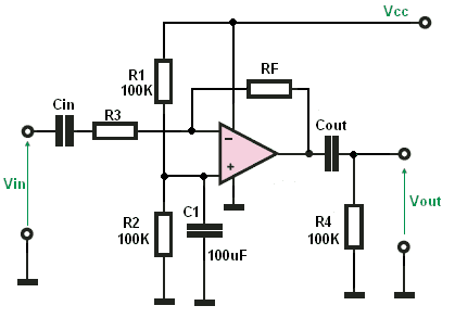
Single-supply inverting op amp amplifier schematic with Vcc at top, R1 and R2 100K biasing the non-inverting input, C1 100uF bypass, RF feedback, Cin and Cout coupling capacitors, R3 and R4 100K, Vin and Vout terminals.
 
The schematic in the first post does set a bias point so to speak but it is not useable if the load is between the output (naturally) and ground. The resistors are not able to carry any significant load current. The schematic in post #4 is definitely workable. I have used it or something similar many times.
 
Averagesupernova said:
The schematic in post #4 is definitely workable. I have used it or something similar many times.
Yep. Here a Texas Instruments Application Report with a collection of Single-Supply Op-Amp Circuits.

"www.eng.yale.edu/ee-labs/morse/compo/sloa058.pdf"
 
Last edited by a moderator:
That's what I have been doing in the last few months! I am designing electronics inside guitar and guitar effect pedals. They all use one 9V battery only. I just put the power across the op-amp like your picture and use a voltage divider to get half voltage for biasing the input of the op-amp like what Jony130's post.
 
yungman said:
That's what I have been doing in the last few months! I am designing electronics inside guitar and guitar effect pedals.

sounds like a good gig.

do you or have you worked on any digital effects devices?

can you tell us what some of these stomp boxes are?

L8r,

r b-j
 
Jony130 said:
Well these resistor create a circuit that is called "virtual ground".
Every real life "active device" to work properly as an amplifier supplied from a single source need proper bias circuit.
When you use BJT as a CE amplifier, you use a voltage divider to bias the active device somewhere in the "linear region".
In case of single supply op amp you have to do the same think. You need to bias the op amp somewhere in the middle of his "linear region". And this resistor provide proper DC bias for Op amp.

Circuit schematic of a single-supply inverting op amp amplifier with Vin coupled through Cin and R3, R1 and R2 100K biasing divider, C1 100uF to ground, feedback resistor RF, output coupled through Cout to R4 100K load and Vout.

I am familiar with the need for biasing networks when working with active amplifiers, I'm just not seeing how the resistors in the original post provide any type of biasing at all.

Regardless of the value of R1, the terminals labeled Vcc and Vee are going to sit at the voltages on positive and negative terminals of the battery. How is that providing any form of biasing at all?

The only thing I can see is that the resistors provide one with a point to ground the circuit.
 
rbj said:
sounds like a good gig.

do you or have you worked on any digital effects devices?

can you tell us what some of these stomp boxes are?

L8r,

r b-j

One is a Distortion pedal that I put my own twist on the clipping circuit. The major one is inside the guitar that I cannot review at this point. In fact I am very close of completing the patent application to submit to the USPTO this week or latest next. I am too cheap to pay thousands of dollars to have a patent attorney to do it. I spent the last half a year not only working on the circuits, also learning how to write the patent. It'll still cost me like $1800 just for the whole process if I am lucky enough that they grant me the patent.

I am not comfortable enough in DSP to do anything in digital. That's where you're the man.:smile:
 
jegues said:
I am familiar with the need for biasing networks when working with active amplifiers, I'm just not seeing how the resistors in the original post provide any type of biasing at all.

Regardless of the value of R1, the terminals labeled Vcc and Vee are going to sit at the voltages on positive and negative terminals of the battery. How is that providing any form of biasing at all?

The only thing I can see is that the resistors provide one with a point to ground the circuit.

The original circuit was not meant to be complete.

The one quoted in your post shows the original two resistors as R1 and R2.

Because the previously negative line is now grounded then the non-inverting "+" input to the opamp now needs to be held at half the supply voltage.

Another consequence of this is that there has to be a capacitor in series with the input because the linear region of the opamp is now near the half voltage point of the opamp supply (half of 36 volts) and the input may not be at +18 volts or so.
 
jegues said:
I am familiar with the need for biasing networks when working with active amplifiers, I'm just not seeing how the resistors in the original post provide any type of biasing at all.

Regardless of the value of R1, the terminals labeled Vcc and Vee are going to sit at the voltages on positive and negative terminals of the battery. How is that providing any form of biasing at all?

The only thing I can see is that the resistors provide one with a point to ground the circuit.

it defines that ground is midway between the positive and negative terminals of the battery. that's all it does.
 
vk6kro said:
The original circuit was not meant to be complete.

That's all I needed to know.