Pumping power calculation of a vertical closed-loop system

AI Thread Summary
The discussion centers on calculating the pumping power required for a vertical closed-loop system where fluid density and pressure drop vary due to temperature changes. It emphasizes the need to consider both frictional and hydrostatic forces when determining the pressure differential for the pump. The participants note that while hydrostatic pressure differences can aid fluid circulation, neglecting this factor could overlook critical aspects of system dynamics. They also highlight the importance of accounting for worst-case scenarios, such as flow restrictions and trapped air, in pump power calculations. Overall, a comprehensive approach that includes safety factors is essential for accurate pumping power assessment.
argeus
Messages
2
Reaction score
0
TL;DR Summary
pumping power calculation of a vertical closed-loop system assuming the hydrostatic term
Hi there,
I hope that somebody can help me with this.. Any response is much appreciated!

Let's have a vertical closed-loop system where the fluid circulates using the pump. The temperature in both sections gradually changes (the upcomer section is heated up) so that the densities, velocities, and pressure drop change as well. Hence, it would be beneficial to split the geometry into horizontal sections; each section (downcomer and upcomer) is divided into a certain number of elements, each of the same height. The point is to calculate the pumping power needed for fluid circulation. The total power is calculated per partes, i.e. for each ith row separately and then simply summed together.

1677502151535.png


For any single ith row, the pumping power equation (w/o hydrostatic term) yields:
1677502566704.png

Note that subscript a refers to a downcomer and subscript b to an upcomer, respectively. Symbol m refers to the mass flow rate, ρ is density and Δp is the pressure drop across the element in the ith row as per Darcy friction eq.
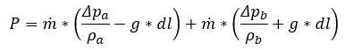
Now assuming a hydrostatic pressure due to the changing density, one gets:
1677502594418.png

Simply, g denotes gravitational acceleration, and the term dl refers to the height of the element in the ith row.
Rearranging a bit:
?hash=1292ae7e36b7eaa26def673fa23d82f0.png

Since the mass flow is the same in both channels, we finally get:
1677502657295.png

Does this mean that the pumping power is independent of the hydrostatic pressure in the closed loop even when the fluid densities in both vertical channels differ? This does not seems correct to me, however, simply cannot find where I'm going wrong..
 

Attachments

  • 1677502617665.png
    1677502617665.png
    1.6 KB · Views: 129
Last edited:
Engineering news on Phys.org
Welcome @argeus !
Pumping required power depends only on fluid flow and pressure differential between inlet and outlet of the pump.
 
argeus said:
Does this mean that the pumping power is independent of the hydrostatic pressure in the closed loop even when the fluid densities in both vertical channels differ?
Rewriting your equation:
$$P = \rho_a \dot{V}_a\frac{\Delta P_a}{\rho_a} + \rho_b \dot{V}_b\frac{\Delta P_b}{\rho_b}$$
Where ##\rho_a \dot{V}_a = \rho_b \dot{V}_b =\dot{m}##. Simplifying:
$$P = \dot{V}_a\Delta P_a + \dot{V}_b\Delta P_b$$
 
Dear Lnewqban,

Thank you for your reply. This is completely true and it matches the first eq. However, the question of how the pressure differential should be calculated remains open. I would guess that it consists of two terms, i.e. frictional forces and hydrostatic forces. If the temperature in the upcomer section is higher (because this section is heated), the density decreases and the hydrostatic balance should promote fluid flow. This is how thermosiphons (aka heat pipes) work. In a specific case, the hydrostatic force difference could balance the frictional forces so that a natural circulation in the closed-loop system is established and no pump is needed. For instance, the geometrical integrity of the Trans-Alaska Pipeline System in a permafrost environment is maintained using such heat pipes. So neglecting the hydrostatic term indicates to me that I've just overlooked something..
 
That difference of temperatures, if substantial and continuous due to good heat transfer on both halves of the loop, may help your pump.
If most thermal energy does not remain in the fluid, something else is needed to stablish and keep a flow, overcoming friction and turbulence.
There is phase change in a heat pipe, you don’t have that in your system.

Nevertheless, at start up, that T differential may not be there, and your pump will need to have increased power to overcome friction of the system at an intermediate temperature.

If you have valves, expansion tanks, aireators, thermometers, coils, etc. in your loop, you will need to calculate pump power for worst conditions (full flow and restricted flow with all closed valves, restricted coils, air pockets traped in horizontal pipes, etc.).
Therefore, a safety factor should be included in your calculations as well.
 
Posted June 2024 - 15 years after starting this class. I have learned a whole lot. To get to the short course on making your stock car, late model, hobby stock E-mod handle, look at the index below. Read all posts on Roll Center, Jacking effect and Why does car drive straight to the wall when I gas it? Also read You really have two race cars. This will cover 90% of problems you have. Simply put, the car pushes going in and is loose coming out. You do not have enuff downforce on the right...
I'm trying to decide what size and type of galvanized steel I need for 2 cantilever extensions. The cantilever is 5 ft. The space between the two cantilever arms is a 17 ft Gap the center 7 ft of the 17 ft Gap we'll need to Bear approximately 17,000 lb spread evenly from the front of the cantilever to the back of the cantilever over 5 ft. I will put support beams across these cantilever arms to support the load evenly
Thread 'Physics of Stretch: What pressure does a band apply on a cylinder?'
Scenario 1 (figure 1) A continuous loop of elastic material is stretched around two metal bars. The top bar is attached to a load cell that reads force. The lower bar can be moved downwards to stretch the elastic material. The lower bar is moved downwards until the two bars are 1190mm apart, stretching the elastic material. The bars are 5mm thick, so the total internal loop length is 1200mm (1190mm + 5mm + 5mm). At this level of stretch, the load cell reads 45N tensile force. Key numbers...
Back
Top