chevique
- 4
- 0
- TL;DR
- I have completed a motion study using SolidWorks to calculate the force required to steer tires in a certain amount of time. I am crunching numbers to determine the mechanical advantage provided by a steering linkage to demonstrate to my supervisor that the motion study makes sense.
It appears that I am unable to attach any images here, so I'll do my best to paint a picture for you.
I completed a motion study using SolidWorks to calculate the force required to steer tires in a certain amount of time. I am confident in the motion study, but I need to complete a separate calculation to instill confidence in the motion for my manager.
I have completed a lot of work, and the one thing I keep getting hung up on is how to calculate the mechanical advantage. Simple, right? But the design, from what I've seen, is not typical. I have good reason to believe there is a mechanical advantage because the calculated kingpin torque far exceeds what the motion study simulated. The calculated kingpin torque was calculated using the length of the "effective radius arm." The effective radius arm is defined as the distance between the center of the kingpin axis and the line formed between one point and its mirror point on the circumference of rotation parallel to the kingpin axis.
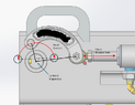
I have a double-ended cylinder attached to a steering linkage on either side. The linkage converts the linear motion of the steering cylinder to the rotational motion of the tire assembly, which rotates about its kingpin axis. However, the linkage does not directly connect to the kingpin - this is the design oddity I alluded to. Instead, the linkage is attached to another pin - call it the prince pin - on the tire assembly that is offset by a fixed radius. It is this pin that rotates itself and the tire assembly about the kingpin.
Now, I am wondering if I have to separate the idea of the lever arm from the that of the effective radius arm. The length of the effective radius arm correlates very well with the simulated changes in force, but it doesn't suffice to explain the torque. One thing that does seem to make the numbers appear reasonable is if I identify the lever arm as being the distance from the kingpin axis to the point where the cylinder attaches to the linkage. Though this makes the numbers seem nice, I am doubtful. The way I see it the, the force applied to the cylinder's pin is transferred over to the prince pin. It is through the prince pin that the force acts on the tire assembly; hence why I'm hesitant to separate the notion of the lever arm from the effective radius arm.
Or could the distance between the prince pin and the cylinder pin be the lever arm? If so, would that make the prince pin a fulcrum and the distance from it to the kingpin the load arm?
Anyway, a lot of information. I hope that I was clear enough. A point in the right direction will be greatly appreciated.
Thank you so much for taking the time to read this!
I completed a motion study using SolidWorks to calculate the force required to steer tires in a certain amount of time. I am confident in the motion study, but I need to complete a separate calculation to instill confidence in the motion for my manager.
I have completed a lot of work, and the one thing I keep getting hung up on is how to calculate the mechanical advantage. Simple, right? But the design, from what I've seen, is not typical. I have good reason to believe there is a mechanical advantage because the calculated kingpin torque far exceeds what the motion study simulated. The calculated kingpin torque was calculated using the length of the "effective radius arm." The effective radius arm is defined as the distance between the center of the kingpin axis and the line formed between one point and its mirror point on the circumference of rotation parallel to the kingpin axis.
I have a double-ended cylinder attached to a steering linkage on either side. The linkage converts the linear motion of the steering cylinder to the rotational motion of the tire assembly, which rotates about its kingpin axis. However, the linkage does not directly connect to the kingpin - this is the design oddity I alluded to. Instead, the linkage is attached to another pin - call it the prince pin - on the tire assembly that is offset by a fixed radius. It is this pin that rotates itself and the tire assembly about the kingpin.
Now, I am wondering if I have to separate the idea of the lever arm from the that of the effective radius arm. The length of the effective radius arm correlates very well with the simulated changes in force, but it doesn't suffice to explain the torque. One thing that does seem to make the numbers appear reasonable is if I identify the lever arm as being the distance from the kingpin axis to the point where the cylinder attaches to the linkage. Though this makes the numbers seem nice, I am doubtful. The way I see it the, the force applied to the cylinder's pin is transferred over to the prince pin. It is through the prince pin that the force acts on the tire assembly; hence why I'm hesitant to separate the notion of the lever arm from the effective radius arm.
Or could the distance between the prince pin and the cylinder pin be the lever arm? If so, would that make the prince pin a fulcrum and the distance from it to the kingpin the load arm?
Anyway, a lot of information. I hope that I was clear enough. A point in the right direction will be greatly appreciated.
Thank you so much for taking the time to read this!