Understanding and Troubleshooting Handlebar Load Calculations

  • #1
nateTheaweseome
14
2
TL;DR Summary
Calculated handle bar pulling force to be significantly lower than what I measured in real life; This is attached to 2 brake cables, each connected to one end of a gas piston (tension).
Hey all,

I'm either overthinking it or too tired but this problem should be an easy one to figure out but I'm stumped embarrassingly.

1700627207223.png

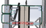
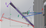
Say in the photo above is a lever arm. I'm trying to backtrack to calculate the force a user must input (yellow) against a force (red). It can pivot around the hinge, and when I calculate the Fr by summing moments around the pivot and solving for Fr, I get around 14lbf. This is designed so that Fp stays horizontal for the range of motion on the arm (not meant to go completely flat).

Now, this doesn't make sense because in real life, I measured this to be about 70lbf...Granted, several things could be wrong here:
1. I screwed up my moment equation (the 40lbf doesn't have a component in Y does it?)
2. I'm thinking this the wrong way
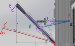
3. The Fp value is wildly wrong. It's a long story but TL;DR That force is coming from 2 different brake cables, attached to both ends of a tension gas piston (rated at 20lbf compression, 34lbf extension). The way I got 40lbf is that when the gas piston is not displaced, the force is around 20lbf, and multiply that by 2 since there's two brake cables attached to both ends of the piston, so the lever at the mounting point will see 40lbf. Now as I understand the compression force increases as displacement increases like a spring but even when I change the total Fp value to be 68lbf, it's no where near what I measured in real life.

I'm kinda stumped so any help would be great.
 
Engineering news on Phys.org
  • #2
I will try to get you on the right path without just giving you any answers.
As I understand it, the pistons and brake cables are not shown in the diagram.

Foot-pounds are units of energy, not force.
So, I am suspecting you are not describing the problem perfectly.
I suggest that when you are working with work or energy, you use a letter other than F.

If 40 foot-pounds of work is applied to the cables, you should expect 40 foot-pounds applied to the lever - presuming, of course, that the device is properly lubricated.
 
  • #3
.Scott said:
Foot-pounds are units of energy, not force.
The lbf = pound⋅foot can be an energy unit, or an engineering moment = a physics torque.
In this case it is specified to be a moment, which is a circular force.
The SI unit of torque is the N⋅m .
 
  • #4
Where is the pivot or hinge in the diagram?
Where are the points of attachment to the tension gas piston.
The 40 lbf shown in red is not being applied tangentially to the lever pivot, so it is not a torque.
Am I correct in thinking that lbf here stands for 40 "pounds force" ?
 
  • #5
Baluncore said:
Where is the pivot or hinge in the diagram?
Where are the points of attachment to the tension gas piston.
The 40 lbf shown in red is not being applied tangentially to the lever pivot, so it is not a torque.
Am I correct in thinking that lbf here stands for 40 "pounds force" ?
The pivot is at Point A.

The point of attachment to the brake cables, which is connected to the gas piston is what Fb represents. It's really attached to that hinged point that Fb goes across.

40lbf in red has a height displacement of 5.79"...I imagined that if I drew a dotted line across this force vector, it would create a moment around A (Fb * 5.79). Just like if I decomposed Fp into Fpx and Fpy vectors, Fpx would create a moment about A.

Yeah that was what I was thinking for 40 pounds force...was I wrong for the units?
1700661408968.png
 
Last edited:
  • #6
.Scott said:
I will try to get you on the right path without just giving you any answers.
As I understand it, the pistons and brake cables are not shown in the diagram.

Foot-pounds are units of energy, not force.
So, I am suspecting you are not describing the problem perfectly.
I suggest that when you are working with work or energy, you use a letter other than F.

If 40 foot-pounds of work is applied to the cables, you should expect 40 foot-pounds applied to the lever - presuming, of course, that the device is properly lubricated.
Thanks for helping.

The pistons/brake cables are represented by the horizontal force Fb in the new drawing.

Yeah maybe I am unclear about the units here. This is the gas piston, and the "Compression Force, lbs" is 20.
 
  • #7
1700668562113.png


So there is a gas cylinder (strut) where the purple arrow is?
 
  • #8
erobz said:
View attachment 335958

So there is a gas cylinder (strut) where the purple arrow is?
1700668842227.png

Well, being specific, there are two brake cables (sketched out in green). Each brake cable is mounted to a different end on the gas piston (red rectangle). The functionality of this arm is that when you pull down, it'll force the gas piston to separate/expand, and when you release, it'll automatically close.
 
  • #9
nateTheaweseome said:
View attachment 335959
Well, being specific, there are two brake cables (sketched out in green). Each brake cable is mounted to a different end on the gas piston (red rectangle). The functionality of this arm is that when you pull down, it'll force the gas piston to separate/expand, and when you release, it'll automatically close.
Please draw the extended cylinder in its orientation. I'm having trouble imagining how you (efficiently) extend the cylinder in the vertical direction by applying a lateral force.
 
  • #10
erobz said:
Please draw the extended cylinder in its orientation. I'm having trouble imagining how you (efficiently) extend the cylinder in the vertical direction by applying a lateral force.
1700669488441.png

Should've made it more clearer my bad.

The piston is mounted horizontally, on two steel extrusions, riding on 2 linear bearings (you can see the top roller rail in the photo). The gas piston will automatically have the extrusions stay closed, but when I pull on the lever, it forces the gas piston to extend out, thus opening the steel extrusions.

Brake cable is rigidly mounted at two points near the lever arm and the steel extrusion (not shown in the photo), allowing me to make this movement. It works since it's already built, but the pulling force is ridiculous so I'm trying to improve it.
 
  • #11
nateTheaweseome said:
View attachment 335960
Should've made it more clearer my bad.

The piston is mounted horizontally, on two steel extrusions, riding on 2 linear bearings (you can see the top roller rail in the photo). The gas piston will automatically have the extrusions stay closed, but when I pull on the lever, it forces the gas piston to extend out, thus opening the steel extrusions.

Brake cable is rigidly mounted at two points near the lever arm and the steel extrusion (not shown in the photo), allowing me to make this movement. It works since it's already built, but the pulling force is ridiculous so I'm trying to improve it.
I'm sorry, this is hard to get my head around (maybe someone else can see it). The cables wrap around the outside of that frame? Give us a top view.

EDIT: Really, lets just be thorough have the standard engineering views.
 
  • #12
erobz said:
I'm sorry, this is hard to get my head around (maybe someone else can see it). The cables wrap around the outside of that frame? Give us a top view.
1700670287094.png

1700670494711.png


Not sure if the top down view will help lol but I also included an iso view. The black cable was a crude attempt to model the length of the brake cable but I highlighted it in green anyways.

The blue stars represent where the brake cable fittings are rigidly mounted.
 

Attachments

  • 1700670387508.png
    1700670387508.png
    72.4 KB · Views: 32
  • #13
nateTheaweseome said:
View attachment 335961
View attachment 335963

Not sure if the top down view will help lol but I also included an iso view. The black cable was a crude attempt to model the length of the brake cable but I highlighted it in green anyways.

The blue stars represent where the brake cable fittings are rigidly mounted.
OK, I see it. So, what is the tension in each cable ignoring friction in the cable housing?
 
  • #14
erobz said:
OK, I see it. So, what is the tension in each cable ignoring friction in the cable housing?
1700671078202.png

So my thought process was, if the compression force initially is 20lbs when the assembly is closed, the tension in each cable housing would be 20lbs (gradually increasing to 34lbs once max stroke is hit).

Thus, the lever arm would see double that, which is why I initially chose 40lbs.
 
  • #15
nateTheaweseome said:
View attachment 335964
So my thought process was, if the compression force initially is 20lbs when the assembly is closed, the tension in each cable housing would be 20lbs (gradually increasing to 34lbs once max stroke is hit).

Thus, the lever arm would see double that, which is why I initially chose 40lbs.
The way I see it keeps the parts closed with 20 lbf.

1700671766335.png


then as you apply load, each cable increases to 34 lbf at full extension:

1700671982903.png
 
  • #16
erobz said:
The way I see it keeps the parts closed with 20 lbf.

View attachment 335965

then as you apply load, each cable increases to 34 lbf at full extension:

View attachment 335967
Okay so it sounds like the force value I chose (40lbf initially for the lever arm since each brake cable is mounted to that hinge) was on the right track then.

So it sounds like my calculations for the pulling force was wrong by setting up my moments incorrectly?
 
  • #17
nateTheaweseome said:
Okay so it sounds like the force value I chose (40lbf initially for the lever arm since each brake cable is mounted to that hinge) was on the right track then.

So it sounds like my calculations for the pulling force was wrong by setting up my moments incorrectly?

Not there yet...What is the tension in each cable at in the fully extended position? Your end goal is to fully open them correct?
 
  • #18
erobz said:
Not there yet...What is the tension in each cable at in the fully extended position? Your end goal is to fully open them correct?
For each brake cable at fully extended position, wouldn't it be 34lbs?
 
  • #19
nateTheaweseome said:
For each brake cable at fully extended position, wouldn't it be 34lbs?
Yeah, so ##F_b## ( acting on the lever arm ) in the fully extended position is?
 
  • #20
erobz said:
Yeah, so ##F_b## ( acting on the lever arm ) in the fully extended position is?
68lbf correct?
 
  • Like
Likes erobz
  • #21
Yeah, that's approximate. To be accurate, in the fully extended position draw the forces ( magnitude 34 lbf each ) acting as they actually act on the lever w.r.t. direction and point of application.
 
  • Like
Likes nateTheaweseome
  • #22
erobz said:
Yeah, that's approximate. To be accurate, in the fully extended position draw the forces ( magnitude 34 lbf each ) acting as they actually act on the lever w.r.t. direction and point of application.
So then ignoring the geometry of the arm (I just realized this is the position of the arm with 20lbf AKA piston closed; when I pull on the lever the angle/lengths will change), is the force decomposition correct?

I am primarily concerned about the decomp for Fb. Say the arm in the snapshot is with the piston has reached full stroke and is seeing ~68lbf of tension. When I sum the moments about A, would it make sense to include Fby?

I say yes but just want to double check my setup.
1700677578429.png
 
  • #23
nateTheaweseome said:
So then ignoring the geometry of the arm (I just realized this is the position of the arm with 20lbf AKA piston closed; when I pull on the lever the angle/lengths will change), is the force decomposition correct?

I am primarily concerned about the decomp for Fb. Say the arm in the snapshot is with the piston has reached full stroke and is seeing ~68lbf of tension. When I sum the moments about A, would it make sense to include Fby?

I say yes but just want to double check my setup.
View attachment 335971
No, you want to decompose forces normal and parallel to their lines of action.

1700679236664.png


The important component of ##F_B## is the component normal to the line of action ##r_{B/A}## when summing torques about ##A##.

Just to be clear what you are doing (not taking into account both tensile forces and where they are applied) is less precise. In my opinion there is very little reason to do it half assed when you have all the geometry (3D model) already worked out. But its ultimately your call, just noting that junk in usually equals junk out.
 
Last edited:
  • Like
Likes nateTheaweseome
  • #24
erobz said:
No, you want to decompose forces normal and parallel to their lines of action.

View attachment 335975

The important component of ##F_B## is the component normal to the line of action ##r_{B/A}## when summing torques about ##A##.

Just to be clear what you are doing (not taking into account both tensile forces and where they are applied) is less precise. In my opinion there is very little reason to do it half assed when you have all the geometry (3D model) already worked out. But its ultimately your call, just noting that junk in usually equals junk out.
That's fair. I guess I just wanted to do something quick but you brought up a good point.

1700682396239.png

So based off what you suggested, I sketched out two positions of the arm (Red and Purple represents the 40lbf and 68lbf positions respectively).

Point A is where the end brake cable fitting is secured, and so as the lever is pulled the cable will elongate and rotate about this point. Each Brake Cable max stroke is 3" (essentially meaning a total of 6" displacement on the gas piston).

Point C and C' represents where I'm roughly assuming the brake cable load is. Line ##r_{C/A}## and Line ##r_{C'/A}## represents the actual brake cable line (you can see initially the distance is 7.2" and after max stroke it's 10.2").

Brown vectors represent the cable forces in the normal/tangential directions across the line of action between ##r_{C/D}## and ##r_{C'/D}##

...So aside from the generalized 68lbf at C/C', would you say this is a decent setup for determining the moments around D?
 

Attachments

  • 1700681638600.png
    1700681638600.png
    37.8 KB · Views: 25
  • 1700681695674.png
    1700681695674.png
    33.9 KB · Views: 30
  • #25
1700683801647.png


This is what you should be doing:

Figure out this geometry at the furthest position, where the force is the highest.

The cables pass through separate gromets at some distance, so it is not true that the forces are colinear. You can pull all the geometry directly from your model. Figure out what the dashed vectors are in magnitude, and multiply them by their respective moment arms ##|| \vec{r}_{B/A}||##, and ##|| \vec{r}_{B/A}||##, that's the resisting torque to ##F_p## at its moment arm ##|| \vec{r}_{P/A}||##.
 
  • Like
Likes nateTheaweseome
  • #26
These gas springs act also as gas dampers:

https://www.explainthatstuff.com/gassprings.html said:
Gas springs as dampers

One thing you'll notice about gas springs is that they work slowly and smoothly. The end of the piston is designed so the fluid inside the cylinder (gas and liquid) can flow through or around it very slowly. Different springs are designed in various different ways and some pistons are arranged so the fluid will flow more quickly past them when the spring moves in one direction than when it moves the opposite way. For example, when the piston is compressed into the cylinder, the end of the piston may be designed to close up a valve so fluid can flow through it only very slowly, reducing the speed at which the piston can move. When the piston moves the other way, the valve can be designed to open up so fluid will travel past it more quickly, allowing the piston to move much faster. Gas springs are usually designed with a particular size of load in mind so they expand very smoothly at a particular rate (so many centimeters or inches per second).
So the fully compressed force may be 20 lb and the fully extended force may be 34 lb, but the force of the moving piston in between can be much much greater. Damping depends on piston velocity.

Does your 70-lb force stabilize to a lower value when holding the piston still?
 
  • #27
jack action said:
These gas springs act also as gas dampers:So the fully compressed force may be 20 lb and the fully extended force may be 34 lb, but the force of the moving piston in between can be much much greater. Damping depends on piston velocity.

Does your 70-lb force stabilize to a lower value when holding the piston still?
Fair point, but note that the OP is struggling to calculate equilibrium forces at this time...

I'll step out of the way.
 
  • #28
erobz said:
Fair point, but note that the OP is struggling to calculate equilibrium forces at this time...

I'll step out of the way.
Well thank you for clarifying this for me though.
 
  • Like
Likes erobz
  • #29
jack action said:
These gas springs act also as gas dampers:So the fully compressed force may be 20 lb and the fully extended force may be 34 lb, but the force of the moving piston in between can be much much greater. Damping depends on piston velocity.

Does your 70-lb force stabilize to a lower value when holding the piston still?
I will need to try that out next time I'm working on the device.
 

What is handlebar load calculation?

Handlebar load calculation refers to the process of determining the amount of force exerted on a bicycle's handlebars during various riding conditions. This includes the weight directly applied by the rider's hands, as well as dynamic loads generated by riding activities such as turning, braking, and riding on uneven surfaces.

Why is it important to calculate handlebar load?

Calculating handlebar load is crucial for several reasons. It helps in designing handlebars that can withstand the forces during normal and extreme riding conditions without failing. It ensures rider safety by preventing handlebar breakage or deformation. Additionally, it aids in optimizing the handlebar's material and geometry for comfort, control, and performance.

What factors influence handlebar load?

Several factors influence handlebar load including the rider's weight, riding style, handlebar geometry, type of bicycle, and the terrain. For instance, mountain bikes experience higher loads due to rough terrains compared to road bikes. The material and construction of the handlebar also affect how it handles loads.

How can handlebar load be measured or calculated?

Handlebar load can be measured using strain gauges attached directly to the handlebar, which record the strain experienced by the handlebars under various conditions. Alternatively, computational methods such as finite element analysis (FEA) can be used to simulate and calculate loads under different scenarios, providing a more comprehensive understanding of the stresses involved.

What are common issues in handlebar load calculations and how can they be resolved?

Common issues in handlebar load calculations include inaccuracies in data collection, such as improper placement of strain gauges, and errors in simulation models. To resolve these, ensure precise setup of measurement instruments and verify the accuracy of simulation parameters and models by comparing with experimental data. Regular calibration of equipment and updating software and models based on the latest research can also help maintain accuracy in calculations.

Similar threads

  • Mechanical Engineering
Replies
1
Views
2K
  • Mechanical Engineering
2
Replies
46
Views
4K
Replies
4
Views
2K
Replies
9
Views
1K
Replies
36
Views
7K
  • Mechanical Engineering
Replies
9
Views
3K
  • Mechanical Engineering
Replies
8
Views
10K
  • Introductory Physics Homework Help
Replies
2
Views
1K
  • Mechanical Engineering
Replies
1
Views
7K
  • Introductory Physics Homework Help
Replies
5
Views
2K
Back
Top