LagCompensator
- 24
- 1
1. Problem Statement:
A 4-pole, star-connected, 50 Hz, 11kV, 40 MVA turbogenerator, with a synchronous reactance of 0.8 p.i., is connected to a power network. This power network can be represented by 11-kV infinite bus with a series reactance of j 0.5 Ω. A voltage regulator adjusts the field current such that alternator terminal voltage remains constant at 11 kV.
2. Relevant equation:
Based on the information above I can write the following equation:
[itex]\overline{E}_ f= \underbrace{\overline{V}_{bus} + jX_{line}\overline{I}_a}_{V_t} + jX_{s}\overline{I}_a[/itex]
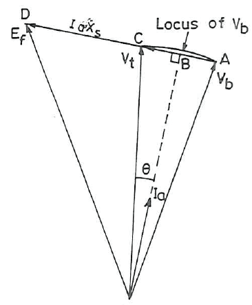
Based on the equation above I can draw the following phasor diagram. I just copied the one drawn in the book, due to my paint skills did not yield a pretty result.
The phasor diagrams draws [itex]I_a[/itex] lagging with respect to [itex]V_t[/itex], and therefore [itex]\theta[/itex] is the angle between them.
My question is: How do I know how to draw [itex]I_a[/itex]? I know that [itex]I_a[/itex] should atleast be lagging [itex]V_t[/itex] at lagging power factor, but could it not also be drawn lagging with respect to [itex]V_b[/itex] and then [itex]\theta[/itex] is the angle between [itex]V_b[/itex] and [itex]\theta[/itex]?
I guess [itex]\theta[/itex] is defined from [itex]V_t[/itex] is because [itex]V_t[/itex] is chosen as reference phasor. But I am still confused by how [itex]I_a[/itex] is placed.
Hope I made myself clear, and appreciate any help, best regards.
A 4-pole, star-connected, 50 Hz, 11kV, 40 MVA turbogenerator, with a synchronous reactance of 0.8 p.i., is connected to a power network. This power network can be represented by 11-kV infinite bus with a series reactance of j 0.5 Ω. A voltage regulator adjusts the field current such that alternator terminal voltage remains constant at 11 kV.
2. Relevant equation:
Based on the information above I can write the following equation:
[itex]\overline{E}_ f= \underbrace{\overline{V}_{bus} + jX_{line}\overline{I}_a}_{V_t} + jX_{s}\overline{I}_a[/itex]
The Attempt at a Solution
:[/B]Based on the equation above I can draw the following phasor diagram. I just copied the one drawn in the book, due to my paint skills did not yield a pretty result.
The phasor diagrams draws [itex]I_a[/itex] lagging with respect to [itex]V_t[/itex], and therefore [itex]\theta[/itex] is the angle between them.
My question is: How do I know how to draw [itex]I_a[/itex]? I know that [itex]I_a[/itex] should atleast be lagging [itex]V_t[/itex] at lagging power factor, but could it not also be drawn lagging with respect to [itex]V_b[/itex] and then [itex]\theta[/itex] is the angle between [itex]V_b[/itex] and [itex]\theta[/itex]?
I guess [itex]\theta[/itex] is defined from [itex]V_t[/itex] is because [itex]V_t[/itex] is chosen as reference phasor. But I am still confused by how [itex]I_a[/itex] is placed.
Hope I made myself clear, and appreciate any help, best regards.