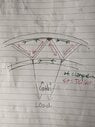
Tension/compression in curved truss? (Diagram attached)
- Context: Undergrad
- Thread starter Smilemore
- Start date
-
- Tags
- Truss
Click For Summary
SUMMARY
The discussion centers on the tension and compression forces within a curved truss structure, particularly when subjected to inward loads from cables. The participants highlight that the truss is statically indeterminate, complicating the analysis of stress distribution. A specific scenario is proposed where the central spokes of the truss are uniformly tightened, prompting a discussion on the resulting stress patterns in the truss members, which behave like springs under load.
PREREQUISITES- Understanding of statically indeterminate structures
- Familiarity with truss analysis techniques
- Knowledge of stress and strain concepts in materials
- Basic principles of mechanics of materials
- Research methods for analyzing statically indeterminate structures
- Study the behavior of truss members under varying loads
- Learn about the principles of elasticity and material deformation
- Explore software tools for structural analysis, such as SAP2000 or ANSYS
Structural engineers, civil engineering students, and professionals involved in the design and analysis of truss systems will benefit from this discussion.
Similar threads
- · Replies 4 ·
High School
What is tension and how does it affect a rope?
- · Replies 2 ·
High School
Understanding air flow and resistance
- · Replies 3 ·
- · Replies 3 ·
Undergrad
Why are these pulleys equivalent?
- · Replies 16 ·
- · Replies 6 ·
High School
A scenario of non-uniform circular motion
- · Replies 4 ·
Undergrad
Tensile and compressive forces
- · Replies 2 ·
- · Replies 13 ·