Gagan
- 3
- 0
I apologize in advance for any errors in my concepts or assumptions. Feel free to correct me wherever I am wrong. Thanks in advance for the help.
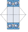
There is a vertical shaft which will be operated at around 600 rpm (N) which can be achieved in 2 seconds (or even 4 just an assumption). The shaft is held by two angular contact ball bearings. I have attached a sketch for further clarification on how the setup looks like (sorry for the bad sketch). The shaft is rotated by a motor via a belt drive mechanism. The pulley radius on both shaft and motor is same so the transmission ratio is 1:1. Shaft material is AISI304.

I need to calculate the torque required by the motor to rotate this shaft which is summation of all the torques generated by the rotating shaft.
The shaft weights 0.7-0.8 Kg. Each bearing weighs 0.15 Kg. I don't know if the weight of the housing is also relevant or not but it is 4 Kgs incase it is required. I already calculated torque due to inertia which is pretty straightforward as follows:
T (in) = I * α
Moment of inertia (I) = 0.5 * MR^2 (if solid, in reality it is hollow but keeping the calculations simple for now)
angular velocity: ω = 2π N /60 = 20π rad/s
angular acceleration: α = dω/time = 10π rad/s^2
Now, since we know this is not the only torque which motor has to resist, there are frictional torque generated by both the bearings. The formula for frictional torque can be approximated for angular contact bearings to:
T (fr) = 0.5 * μ * radial load (N) * bearing bore (m)
μ = 0.002 for angular contact ball bearings (this is low because there is lubrication and non-contact seals) so the frictional force in reality acting between shaft and the lubricant
(Source: https://www.amroll.com/friction-frequency-factors.html)
I calculated the radial loads acting (perpendicular) on bearing face from rotating shaft considering they are centrifugal but I am assuming I am wrong here. I do know, this is very less and can be neglected but I am considering it because it can be significant relative to the inertial torque. I want to know how I can calculate the radial loads acting on the bearing. Also, if there are any other loads acting on the bearings (apart from axial load i.e. mass * gravity), you're welcome to tell me
I know there are other considerations like belt transmission efficiency (80-90%) , safety factor (2-2.5) etc. But, I will account for them at the last once I have the required torque (from inertia and friction). Nevertheless, do tell me if there are any other crucial considerations that I should account for.
Feel free to make assumptions (can consider shaft with same cross-section diameter all along the length) because I am looking for assistance on concepts, formulas and how I should approach the problem. All the other details (relevant or not) can be seen in the sketch.
Thanks
Gagan Jain
There is a vertical shaft which will be operated at around 600 rpm (N) which can be achieved in 2 seconds (or even 4 just an assumption). The shaft is held by two angular contact ball bearings. I have attached a sketch for further clarification on how the setup looks like (sorry for the bad sketch). The shaft is rotated by a motor via a belt drive mechanism. The pulley radius on both shaft and motor is same so the transmission ratio is 1:1. Shaft material is AISI304.
I need to calculate the torque required by the motor to rotate this shaft which is summation of all the torques generated by the rotating shaft.
The shaft weights 0.7-0.8 Kg. Each bearing weighs 0.15 Kg. I don't know if the weight of the housing is also relevant or not but it is 4 Kgs incase it is required. I already calculated torque due to inertia which is pretty straightforward as follows:
T (in) = I * α
Moment of inertia (I) = 0.5 * MR^2 (if solid, in reality it is hollow but keeping the calculations simple for now)
angular velocity: ω = 2π N /60 = 20π rad/s
angular acceleration: α = dω/time = 10π rad/s^2
Now, since we know this is not the only torque which motor has to resist, there are frictional torque generated by both the bearings. The formula for frictional torque can be approximated for angular contact bearings to:
T (fr) = 0.5 * μ * radial load (N) * bearing bore (m)
μ = 0.002 for angular contact ball bearings (this is low because there is lubrication and non-contact seals) so the frictional force in reality acting between shaft and the lubricant
(Source: https://www.amroll.com/friction-frequency-factors.html)
I calculated the radial loads acting (perpendicular) on bearing face from rotating shaft considering they are centrifugal but I am assuming I am wrong here. I do know, this is very less and can be neglected but I am considering it because it can be significant relative to the inertial torque. I want to know how I can calculate the radial loads acting on the bearing. Also, if there are any other loads acting on the bearings (apart from axial load i.e. mass * gravity), you're welcome to tell me
I know there are other considerations like belt transmission efficiency (80-90%) , safety factor (2-2.5) etc. But, I will account for them at the last once I have the required torque (from inertia and friction). Nevertheless, do tell me if there are any other crucial considerations that I should account for.
Feel free to make assumptions (can consider shaft with same cross-section diameter all along the length) because I am looking for assistance on concepts, formulas and how I should approach the problem. All the other details (relevant or not) can be seen in the sketch.
Thanks
Gagan Jain
Last edited: