@jojosg, there are a number of issues, so it's complicated to explain. But here is an attempt...
I've written some of your equations from Post 14, so that LaTeX renders them correctly (for me anyway). This required putting a pair of hash symbols (## \# \# ##) at the beginning and end of each equation.
So, the first part of your Post 14 working (with some comments aded) is this:
__________________________________
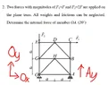
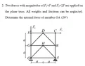
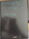
##\sum M_0 = 0##
##-F(2a) + A_y(2a) = 0##
##A_y = F##
That looks OK.
___________________________________
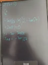
##\sum F_x = 0##
##F + A_x = O_x##
Not really. There is a roller at point A. There is no external horizontal reaction from a (perfect) horizontal roller. So you know in advance that ##A_x=0##..
If you don’t use this fact (that ##A_x=0##), then you have thrown away critical supplied information; this may prevent you from finding the correct answer.
The only 2 horizontal external forces are ##O_x## at point O and ##F_1## at point C.
___________________________________
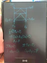
##\sum F_y = 0##
##O_y + A_y = 2F##
That looks OK.
You already found that ##A_y = F##. So it follows that ##O_y=F##. You don't need your next step...
___________________________________
##\sum M_A = 0##
##-F(2a) + 2F(2a) - O_y(2a) = 0##
##F = O_y##
That's OK. but it is an unecessary step, as already noted.
___________________________________
##F = O_x - A_x##
But ##A_x## is known to be zero. See above.
___________________________________
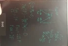
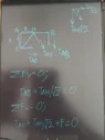
##\sum F_y = 0##
##-2F - \frac{F_{OH}}{\sqrt{2}} = 0##
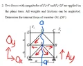
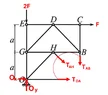
Not clear about this. It looks like you are referring to the system with a cut to remove the bottom-left section.
It appears you have assumed member GO has a tension of 2F and member AO has a tension equal to ##O_x##. That's wrong.
You need to redraw your diagram to show all external forces: carefully examine the Post #13 comments and diagram.
___________________________________
Additional note.
You have marked ##O_x## on a diagram as pointing left. By convention, an unknown x-component is assumed positive (pointing right, in the +x direction). With this corrected, ##O_x = -F##.
You can then (on a subsequent diagram) show this as a force F pointing left. Care is needed to avoid introducing sign-errors.
There may be other issues I've missed.
Minor edits (& again).