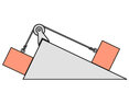
Two masses connected by a rope on a pulley on a ramp

AI Thread Summary
To solve the problem of two masses connected by a rope on a pulley on a ramp, it's essential to create distinct symbols for each mass to avoid confusion. After establishing the free body diagrams, the next step is to write the force balance equations for each mass. These equations can be organized either by separating horizontal and vertical forces or by considering forces parallel and normal to the slopes. This structured approach simplifies the problem and clarifies the forces acting on each mass. Properly defining the variables and equations is crucial for an accurate solution.
runningphysics
Messages
6
Reaction score
3
Homework Statement
If the left-hand slope in the figure makes a 58° angle with the horizontal, and the right-hand slope makes a 32° angle, how should the masses compare if the objects are not to slide along the frictionless slopes?
Relevant Equations
F=ma
I have no clue how to do the problem. I created a free body diagram for each block. I assume that it is simpler than I am making it out to be.
 

Attachments

  • RW-05-19.jpg
    RW-05-19.jpg
    6.3 KB · Views: 124
  • IMG-2503.jpg
    IMG-2503.jpg
    42.5 KB · Views: 121
Physics news on Phys.org
First, use a different symbol for each mass. Calling them both "m" will confuse.

Next, write the force balance equations for each mass.
You can write an equation for each of horizontal and vertical or for parallel to the slope(s) and normal to them. Your choice.
 
Kindly see the attached pdf. My attempt to solve it, is in it. I'm wondering if my solution is right. My idea is this: At any point of time, the ball may be assumed to be at an incline which is at an angle of θ(kindly see both the pics in the pdf file). The value of θ will continuously change and so will the value of friction. I'm not able to figure out, why my solution is wrong, if it is wrong .
Thread 'Voltmeter readings for this circuit with switches'
TL;DR Summary: I would like to know the voltmeter readings on the two resistors separately in the picture in the following cases , When one of the keys is closed When both of them are opened (Knowing that the battery has negligible internal resistance) My thoughts for the first case , one of them must be 12 volt while the other is 0 The second case we'll I think both voltmeter readings should be 12 volt since they are both parallel to the battery and they involve the key within what the...
Back
Top