Uniform rods and disk in static equilibrium

Click For Summary

Discussion Overview

The discussion revolves around a problem involving uniform rods and a disk in static equilibrium, focusing on the forces and moments acting on the system. Participants explore various approaches to analyze the equilibrium conditions, including force balance and torque calculations.

Discussion Character

  • Technical explanation
  • Mathematical reasoning
  • Debate/contested
  • Homework-related

Main Points Raised

  • One participant expresses confusion about the hinge where the rods meet and the overall approach to the problem.
  • Another participant outlines their method for analyzing the forces and moments, suggesting that they are using the correct technique but not arriving at the expected answer.
  • There is a discussion about resolving forces into their vertical components and the implications for equilibrium conditions.
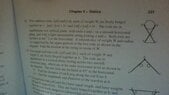
  • Participants question the direction of forces labeled as R in the diagrams, indicating uncertainty about how to determine their orientation.
  • One participant presents a series of equations related to the forces and torques acting on the system, including a calculation for the normal force N and tension T.
  • Another participant suggests that the analysis should focus on external forces acting on the whole object before considering individual components.
  • There are multiple sketches shared to illustrate the forces and moments, with participants discussing the software used for these diagrams.

Areas of Agreement / Disagreement

Participants do not appear to reach a consensus on the correct approach to the problem, with multiple competing views and methods being discussed. Uncertainty remains regarding the resolution of forces and the direction of certain forces in the diagrams.

Contextual Notes

Participants express confusion over the assumptions made regarding force directions and the need to resolve forces into components. There are also unresolved mathematical steps related to the calculations of forces and torques.

markosheehan
Messages
133
Reaction score
0
i am stuck on question 9 can anyone help me out.
thanksView attachment 7225
 

Attachments

  • WIN_20170817_17_31_52_Pro.jpg
    WIN_20170817_17_31_52_Pro.jpg
    91.4 KB · Views: 122
Mathematics news on Phys.org
not 100% sure this is it ... still pondering the hinge where the rods meet.
 
Last edited by a moderator:
skeeter said:
not 100% sure this is it ... still pondering the hinge where the rods meet.
yes your diagram is right. i feel i am using the right technique but i am not getting the right answer

anyway what i did was for the whole system forces left=forces right so R1sina=R2sina
forces up=forces down s1+s2=3w+r1cosa+r2cosa+w+w+w.

then i look at forces on rod ab individually (separate to the whole system). i take moments about point o
i will come back tommorow with the equation i get.

doing anything else than i described will lead you going around in circles and it will lead to equations canceling out
 
$\displaystyle \sum F_y = 0 \implies 2N = 3W \implies N = \dfrac{3W}{2}$

Torques about the hinge for one of the rods ...

$R \cdot 2r + W\cos{\theta} \cdot \dfrac{r}{2} + N \cos{\theta} \cdot 2r = T \sin{\theta} \cdot 2r$$\tan{\theta} = 2 \implies \cos{\theta} = \dfrac{1}{\sqrt{5}} \implies \sin{\theta} = \dfrac{2}{\sqrt{5}}$

$R = \dfrac{W\sqrt{5}}{2}$$\dfrac{W\sqrt{5}}{2} \cdot 2r + W \cdot \dfrac{1}{\sqrt{5}} \cdot \dfrac{r}{2} + \dfrac{3W}{2} \cdot \dfrac{1}{\sqrt{5}} \cdot 2r = T \cdot \dfrac{2}{\sqrt{5}} \cdot 2r$

solving for $T$ ...

$T = \dfrac{17W}{8}$
 
when letting forces up=forces down why did you not resolve the forces R and R into there vertical components?
you were taking forces up=down for the whole system right, not just looking at the two rods?

and my second question is how did you know the direction of R and R in your diagram. how did you it was not the other way around. the system is in equilbrium so there is obviously R going in the opposite direction as well.(Newtons law). i am confused though on which one you are supposed to use though. how are you supposed to know the direction.?

thank you very much
 
markosheehan said:
when letting forces up=forces down why did you not resolve the forces R and R into there vertical components?
you were taking forces up=down for the whole system right, not just looking at the two rods?

I did so to calculate the force R in terms of W.

The forces labeled R in the diagram are the forces acting on the rods by the weight of the disc.

See attached diagram ...

markosheehan said:
... and my second question is how did you know the direction of R and R in your diagram. how did you it was not the other way around. the system is in equilbrium so there is obviously R going in the opposite direction as well.(Newtons law). i am confused though on which one you are supposed to use though. how are you supposed to know the direction.

To calculate the torques about either rod, one needs the forces acting on the rod. As stated earlier, $R$ in my sketch is the force acting on the rod by the weight of the disc. A force pointing in the opposite direction would be the reaction force of the rod acting on the disc.
 
i still can not understand.

i am not sure how you get Rcos(θ)=2/w

if the equation is for the whole system you let all forces up = all forces down .

i would of thought it to be this

N+N=W+W+W+Rcosθ+Rcosθ

we know cosθ=1/\sqrt{5}

then this equals 2N=3w+2R(1/\sqrt{5})

but i do not know what you can substitute R for .i understand the second question. just wondering say we took moments about the center of the disc. does that mean we would be looking at forces on the disc and not the rod so we would take R in the other direction.

i understand this."To calculate the torques about either rod, one needs the forces acting on the rod" but for letting forces up=forces down how did you know the direction of R cause your quote does no longer apply.
 
First step is to only look at the external forces that act on the whole object.
That is, the forces of gravity on each object and the normal forces from the table.
\begin{tikzpicture}[>=stealth]
\draw[ultra thick] (-2,-4) node[above right, xshift=0.2cm] {$\theta$} -- (3,6);
\draw[ultra thick] (2,-4) -- (-3,6);
\draw (-2,-4) -- (2,-4);
\filldraw[thick, fill=lightgray] (0,5) circle ({sqrt(5)});
\draw[red, ultra thick, ->] (0,5) -- node
{W} +(0,-1);
\draw[red, ultra thick, ->] (0.5,1) -- node
{W} +(0,-1);
\draw[red, ultra thick, ->] (-0.5,1) -- node
{W} +(0,-1);
\draw[red, ultra thick, ->] (-2,-4) -- node
{N} +(0,1.5);
\draw[red, ultra thick, ->] (2,-4) -- node
{N} +(0,1.5);
\fill circle (0.1);
\end{tikzpicture}
It follows that $N=\frac 32 W$.

Then we look at each part separately.

For the disk we have:
\begin{tikzpicture}[>=stealth]
\filldraw[thick, fill=lightgray] (0,5) circle ({sqrt(5)});
\draw[red, ultra thick, ->] (0,5) -- node
{W} +(0,-1);
\draw[red, ultra thick, ->] (2,4) -- node[above right] {R} +(-1,0.5);
\draw[red, ultra thick, ->] (-2,4) -- node[above left] {R} +(1,0.5);
\end{tikzpicture}
From this diagram we can deduce $R$.

And for one of the rods we have:
\begin{tikzpicture}[>=stealth]
\draw[ultra thick] (-2,-4) node[above right, xshift=0.2cm] {$\theta$} -- (3,6);
\draw[red, ultra thick, ->] (0.5,1) -- node
{W} +(0,-1);
\draw[red, ultra thick, ->] (-2,-4) -- node
{N} +(0,1.5);
\draw[red, ultra thick, ->] (2,4) node[below right, yshift=-0.1cm] {$\theta$} -- +(1,-0.5) node[below right] {R} ;
\draw[red, ultra thick, dashed, ->] (2,4) -- +(1,0) node
{Rx};
\draw[red, ultra thick, dashed, ->] (2,4) -- +(0,-0.5) node[below] {Ry};
\draw[red, ultra thick, ->] (-2,-4) -- node[below] {T} +(1,0);
\draw[red, ultra thick, ->] (0,0) -- node[below] {Hx} +(1,0);
\draw[red, ultra thick, ->] (0,0) -- node
{Hy} +(0,1);
\fill circle (0.1);
\end{tikzpicture}
Note that force $R$ is equal and opposite to the one for the disk.

At all times we have 3 equations:
$$\sum F_x = 0 \\ \sum F_y = 0 \\ \sum M_{\text{with respect to some hinge}} = 0$$
In particular we can find $T$ by setting up the equation for the moment of inertia with respect to the hinge.​
 
@ I like Serena ...

Nice sketches. What software did you use to make them? I do mine on MS Paint.
 
  • #10
skeeter said:
@ I like Serena ...

Nice sketches. What software did you use to make them? I do mine on MS Paint.

Thanks!

The software is embedded in this forum just like MathJax for formulas.
See: http://mathhelpboards.com/showthread.php?19543-TikZ-pictures
If you click on one of the pictures (or quote the comment), it shows the $\LaTeX$ behind it.
See http://35.164.211.156/tikz/tikzlive.html for an online interactive editor with some templates.
 
  • #11
I like Serena said:
\begin{tikzpicture}[>=stealth]
\draw[ultra thick] (-2,-4) node[above right, xshift=0.2cm] {$\theta$} -- (3,6);
\draw[ultra thick] (2,-4) -- (-3,6);
\draw (-2,-4) -- (2,-4);
\filldraw[thick, fill=lightgray] (0,5) circle ({sqrt(5)});
\draw[red, ultra thick, ->] (0,5) -- node
{W} +(0,-1);
\draw[red, ultra thick, ->] (0.5,1) -- node
{W} +(0,-1);
\draw[red, ultra thick, ->] (-0.5,1) -- node
{W} +(0,-1);
\draw[red, ultra thick, ->] (-2,-4) -- node
{N} +(0,1.5);
\draw[red, ultra thick, ->] (2,-4) -- node
{N} +(0,1.5);
\fill circle (0.1);
\end{tikzpicture}


... for construction of this tikz sketch, you used the coordinates from my MS paint sketch?​
 
  • #12
skeeter said:
... for construction of this tikz sketch, you used the coordinates from my MS paint sketch?

Yep.
 

Similar threads

  • · Replies 2 ·
Replies
2
Views
535
Replies
43
Views
2K
  • · Replies 3 ·
Replies
3
Views
2K
  • · Replies 14 ·
Replies
14
Views
1K
Replies
14
Views
2K
  • · Replies 17 ·
Replies
17
Views
2K
Replies
14
Views
2K
  • · Replies 1 ·
Replies
1
Views
976
Replies
13
Views
2K
  • · Replies 8 ·
Replies
8
Views
3K