Voltage Divider vs Voltage Regulator?

Join the discussion
Ask a follow-up here, or get your own question answered by working scientists, mathematicians and engineers — people, not an autocomplete.
Real named experts · corrections over time · the nuance an AI answer skips
6 replies · 5K views
Vishera
Messages
72
Reaction score
1
I have two questions.

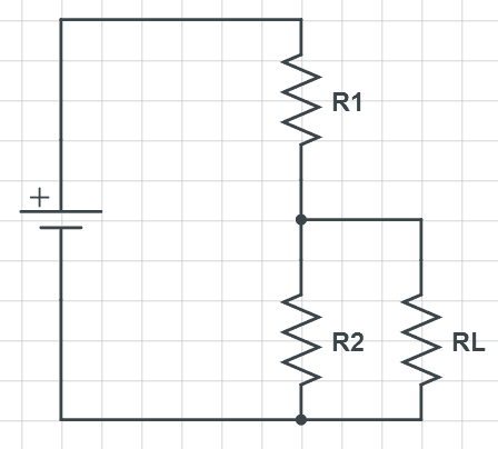
1. A lot of voltage dividers are wired up like this:
OONoyM8.png


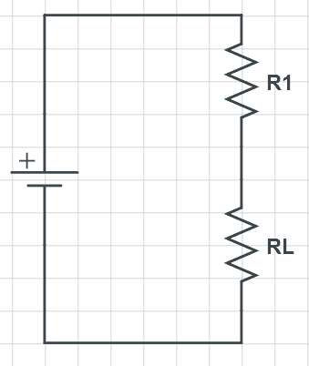
Is there any reason why they can't be wired up like below?
cVaUzy9.png


2. When should a voltage regulator be used instead of a voltage divider?
 
Engineering news on Phys.org
Voltage regulators should be used whenever economically viable because all power going through R2 in fig 1. is completely wasted. But if you are just using the voltage as a signal, say for digital logic, and there isn't any significant current flow, then voltage dividers are perfectly fine.
 
Vishera said:
I have two questions.

1. A lot of voltage dividers are wired up like this:

OONoyM8.png


Is there any reason why they can't be wired up like below?

cVaUzy9.png


2. When should a voltage regulator be used instead of a voltage divider?

i think voltage regulator is way better than voltage divider. although linear regulators burn a lot of energy.
 
linear regulators are actually very efficient.
A regulator should be used wherever possible

Vishera said:
1. A lot of voltage dividers are wired up like this:

OONoyM8.png


Is there any reason why they can't be wired up like below?

cVaUzy9.png

RL=Resistance of the load.
many times it is a variable value.
If your divider was setup in the topology you suggested in your second picture, the voltage across RL would change a lot as RL changed. If it was setup as suggested in the first picture, It would not change as much.

Also when you get to transistors, you will see why it can be advantageous to use the first topology.
 
Both of the diagrams in the OP will work but the voltage across the load is very dependent upon the value of RL. That could be very embarrassing for the function of the circuit being supplied (RL). A voltage regulator will produce the correct voltage at the output by altering the current it supplies, (using a transistor - or equivalent) effectively as a variable R1, to keep the ratio of resistances right for the required output volts. That's a dynamically adjusted voltage divider - if you like.
 
donpacino said:
linear regulators are actually very efficient.
.....

no, linear regulators are quite inefficient

hence its always better to use buck or boost regulator topology, efficiency is substantially improved

to the OP...
circuit 1 is a voltage divider, circuit 2 isn't
voltage divider circuits DONT provide any regulation and as sophiecentaur said ...
voltage across the load is very dependent upon the value of RL.


Dave