Science Advisor
Gold Member
- 4,943
- 1,575
I wasn't.James2018 said:Don't worry, I fixed the circuit.
I wasn't.James2018 said:Don't worry, I fixed the circuit.
C1 and C2 do not allow AC to pass. On one terminal they have full 5 V DC voltage and on the other they have 0 mV. Maybe they are faulty. Only C3 does block 5V of DC and pass 8 mV of AC. Strangely, because they are newly bought just a week ago and by the same manufacturer as C3. I used them in the previous circuit too. Every other component works as intended.Baluncore said:So, do you now hear a quiet frequency in the AM BC band that gets noisy again when you turn off the oscillator?
I connected my multimeter in series between the capacitor and the inductor and it detects 2 uA maximum, not 200 uA of AC. I suppose this is why the radio AM antenna is not perturbed.Baluncore said:A digital multimeter will not measure a 1 MHz voltage or current. That is why you get silly results like 0.1 mV AC.
The circuit I gave you runs on about 200 uA total. That is almost nothing.
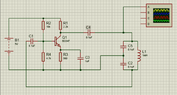
The RF output comes from the magnetic field of the inductor, where there is a 1 MHz current oscillating between ±2.6 mA, plotted below in yellow.
The base voltage is plotted in red, with the emitter voltage in green.
If you disconnect the inductor at the ground end, the oscillator will stop.
Then measure the base voltage, Vb, which will be about 2.5 V.
Also measure the emitter voltage, Ve, which will be about 1.6 V.
There are two capacitors and an inductor that connect to that node. Which one did you try? It is your multimeter that is not perturbed. It is not designed to measure AC current at RF frequencies.James2018 said:I connected my multimeter in series between the capacitor and the inductor and it detects 2 uA maximum, not 200 uA of AC. I suppose this is why the radio AM antenna is not perturbed.
37 turns, 6.4 cm long = 64 mm long. 0.8 cm = 8 mm diameter.James2018 said:no problem I will increase the coil length of the variable inductor so it can have 0.506 uH instead of 1.35 uH to get a resonant frequency of 1.001 MHz.
The wire used to wind the coil is thin steel wire. There is no shorted turn because this wire is elastic and the turns do not touch each other. The entire circuit is made of elastic steel wire except the very thin copper wire bits that connect to the base, collector and emitter of the transistor.Baluncore said:There are two capacitors and an inductor that connect to that node. Which one did you try? It is your multimeter that is not perturbed. It is not designed to measure AC current at RF frequencies.
I believe your coil is too long for its diameter, and the capacitors are too high a value. For an air cored coil, the length should be similar to, or less than the diameter.
What wire have you used to wind the coil? Is it insulated, have you got a shorted turn?
37 turns, 6.4 cm long = 64 mm long. 0.8 cm = 8 mm diameter.
I calculate 1.7255 µH.
If your series capacitors make 50 nF. Then the frequency = 541.8 kHz.
Being at the very edge of the AM BC band, there is a 50% chance the oscillator frequency will not fall in the band.
That is why I suggest 1 MHz as the target.
You don't mean that. Capacitors do not pass DC (infinite impedance).James2018 said:C1 and C2 do not allow AC to pass.
One of my capacitors in my circuit passes AC and blocks DC while the other two block both AC and DC. Or so the multimeter tells me. Maybe the ones not passing AC are flawed or maybe the multimeter has a slow response.sophiecentaur said:You don't mean that. Capacitors do not pass DC (infinite impedance).
James2018 said:C1 and C2 do not allow AC to pass.
A capacitor (value C) has a reactance Xc = 1/2πfC. That will tell you how much current will pass for 1V PD. A few sums can be very useful. What current would the 220pF capacitor pass for 1V at 1MHz? Would your meter detect that - bearing in mind its likely frequency response? (Ignore the phase.)sophiecentaur said:You don't mean that. Capacitors do not pass DC (infinite impedance).
But with 6.3 cm length, 6 turns, 3 cm diameter of insulated copper wire coil I get a 508 nanoHenries inductor which with 50 nF effective capacitance give a resonant frequency of 0.9986 MHz. In this new circuit, the two 100 nF capacitors in series give an effective capacitance of 50 nF.Baluncore said:There are big problems with your tank circuit. The L and C values you have chosen make it difficult for the oscillator to start. You need to wind a higher inductance coil. The way you have it now, the circulating current in the tank would need to be ±250 mA to keep it oscillating, that might be possible if your wire was thick enough, and the capacitors were perfect, but they are not.
There are good reasons to build the tank circuit for 1 MHz using;
C2 = 1 nF ; C3 = 220 pF ; L1 = 120 uH .
MW BC band coils can be wound on toilet roll tubes. For 120 uH you should wind 75 turns, on a 38 mm diameter tube, and spread the coil over a length of 50 mm. That will require 9 metres of wire, but it will work well.
If I use a 470 uH inductor with ferrite core, what capacitance value would I need? By the way they do not really have a 1 nF capacitor anywhere for sale, but I did find a 220 pF capacitor and a 15 nF capacitor.Baluncore said:There are big problems with your tank circuit. The L and C values you have chosen make it difficult for the oscillator to start. You need to wind a higher inductance coil. The way you have it now, the circulating current in the tank would need to be ±250 mA to keep it oscillating, that might be possible if your wire was thick enough, and the capacitors were perfect, but they are not.
There are good reasons to build the tank circuit for 1 MHz using;
C2 = 1 nF ; C3 = 220 pF ; L1 = 120 uH .
MW BC band coils can be wound on toilet roll tubes. For 120 uH you should wind 75 turns, on a 38 mm diameter tube, and spread the coil over a length of 50 mm. That will require 9 metres of wire, but it will work well.
But for 700 KHz I would need two 220 pF connected in series. That I can do. Hopefully if they still have 220 pF capacitors in stock.Baluncore said:For 1 MHz ;
f = 1 / ( 2 * Pi * Sqrt( L * C ) ) hertz.
C = 1 / ( L * ( 2 * Pi * f )^2 ) farad.
C = 53.9 pF.
Is there radio silence somewhere else in the band?James2018 said:Even with two 220 pF connected in series and a 470 uH inductor it still is no radio silence at 700 KHz.
Baluncore said:Is there radio silence somewhere else in the band?
If not, slide the ferrite rod slowly out of the coil, listening for when the oscillator frequency moves up through the band.
Check the battery voltage, 5V; the base voltage, 2.5V; and the emitter voltage, 1.8V .
Why does nothing work for you?
Did you solder the wires or glue them?
Then measure the resistance of the coil with your multimeter.James2018 said:It is for RLC circuit, but for this Collpits oscillator I don't know what the effective resistance is.
I don't believe it worked. The low value resistors stopped the oscillator by over-loading the battery.James2018 said:And yet, I have to mention the previous Collpits oscillator did work, albeit emitting a disorted noisy radio waves because of the low resistances.
The resistance of my coil is 7. 2 Ohms. It gives a quality factor of 287.1 and a frequency of 700 KHz.Baluncore said:Then measure the resistance of the coil with your multimeter.
I don't believe it worked. The low value resistors stopped the oscillator by over-loading the battery.
What voltages did you measure?Baluncore said:Is there radio silence somewhere else in the band?
If not, slide the ferrite rod slowly out of the coil, listening for when the oscillator frequency moves up through the band.
Check the battery voltage, 5V; the base voltage, 2.5V; and the emitter voltage, 1.8V .
Unlike a LED lighting up from this battery, this circuit doesn't even draw any voltage. It says 0 V near the battery. Certainly if this circuit works for other persons, maybe some components I used are flawed.Baluncore said:What voltages did you measure?
I think you mean it does not draw current, because it is open circuit.James2018 said:Unlike a LED lighting up from this battery, this circuit doesn't even draw any voltage. It says 0 V near the battery.
No, I have made the proper circuit by the original diagram and now it works. I have used those 2.2k, 4.7k, 10k and 560 Ohms resistances and it works. The only thing I did change was the tank circuit, with C5 and C2 replaced by 220 pF capacitors and the L1 replaced by the 470 uH inductor.Baluncore said:I think you mean it does not draw current, because it is open circuit.
So the battery is not flat, but the wires are not connected.
How do you join wires to components?
Test the connection resistance with your multimeter.
Your blurry photos show what looks like clear sticky tape being used to hold wires down. The static electricity from the tape, when it is unrolled, may destroy the transistor base junction.