- #1
david90
- 312
- 2
Hi,
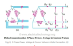
Regarding the picture below, the author calculates L1's current with KCL equation IR-IB = L1. Why is the KCL equation not IR+IB = L1 if the voltage of phase B and Phase R at one point during their cycle can be both positive (Assume positive voltage means current go toward the node)? If Phase B and Phase R voltage are positive then their current move in the same direction and thus IR and IB should have the same signage?
https://www.electricaltechnology.org/2014/09/delta-connection-power-voltage-current.html