Equivalent capacitance of a circuit

In summary: Thank you for your help!In summary, the given circuit consists of five capacitors in a specific arrangement. Using symmetry, it can be simplified into an equivalent circuit with four capacitors, where ∆V2 = 0 due to the symmetry of the circuit. The reasoning behind this simplification can be better understood by redrawing the circuit and analyzing the symmetry of the branches.
  • #1
jolly_math
51
5
Homework Statement
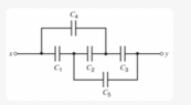
Find the equivalent capacitance between points x and y in the diagram below. Assume that C2 = 10 µF and that the other capacitors are all 4.0 µF.
Relevant Equations
in series: 1/C = 1/C1 + 1/C2
in parallel: C = C1 + C2
1676860916661.png

Why is it that, due to symmetry, ∆V2 = 0 and ∆V1 = ∆V4 = ∆V5 = ∆V3? I don't really understand the reasoning behind the simplification. Thank you.
 
Physics news on Phys.org
  • #2
Is this how you worked the problem?

##C_1## and ##C_2## are in series so we have an equivalent capacitor ##C_{12}##

##C_{12}## and ##C_4## are in parallel so we have an equivalent capacitor ##C_{124}##

##C_3## and ##C_5## are in parallel so we have an equivalent capacitor ##C_{35}##

##C_{124}## and ##C_{35}## are in series so we have an equivalent capacitor ##C_{12345}##
 
  • #3
Callumnc1 said:
##C_1## and ##C_2## are in series so we have an equivalent capacitor ##C_{12}##
No, you can't do that. To be considered in series there must be no other circuit connection between the two.
 
  • Like
Likes ChiralSuperfields and DaveE
  • #4
jolly_math said:
Why is it that, due to symmetry, ∆V2 = 0
It becomes obvious if you redraw the diagram. Remove 2 for the moment and draw the rest in a simple rectangle, then reinstate 2.
 
  • Like
Likes ChiralSuperfields
  • #5
haruspex said:
No, you can't do that. To be considered in series there must be no other circuit connection between the two.
Whoops, sorry @haruspex thank you for picking up on that!
 
  • #6
haruspex said:
It becomes obvious if you redraw the diagram. Remove 2 for the moment and draw the rest in a simple rectangle, then reinstate 2.
Thank you for your reply @haruspex !

I know my diagram is probably drawn incorrectly,
1676865736575.png

What are my mistakes thought?

Many thanks!
 
  • #7
1676869436187.png

Why is it that, due to symmetry, ∆V2 = 0? If I remove V2, C1 and C4 (in parallel) are in series to C3 and C5 (in parallel). When I redraw V2, how I would be able to determine that V2 = 0? Thank you.
 
  • #8
Callumnc1 said:
Thank you for your reply @haruspex !

I know my diagram is probably drawn incorrectly,
View attachment 322555
What are my mistakes thought?

Many thanks!
Completely incorrect.

@haruspex was replying to OP, who at least realizes that ∆V2 = 0 .

Added in Edit:
I had misread OP's question.

OP does not understand the symmetry argument justifying ##\Delta V_2=0## .
 
Last edited:
  • Like
Likes ChiralSuperfields
  • #10
SammyS said:
Completely incorrect.

@haruspex was replying to OP, who at least realizes that ∆V2 = 0 .
Thank you for your reply @SammyS!

Do you please know why ∆V2 = 0?

Many thanks!
 
  • #11
Callumnc1 said:
Thank you for your reply @haruspex !

I know my diagram is probably drawn incorrectly,
View attachment 322555
What are my mistakes thought?

Many thanks!
Take it in steps. First, remove C2, then straighten the rest of them diagram into a simple rectangle with two capacitors in series in the top line and the other two in the bottom.
Post those two.
 
  • Like
Likes ChiralSuperfields and SammyS
  • #12
haruspex said:
Take it in steps. First, remove C2, then straighten the rest of them diagram into a simple rectangle with two capacitors in series in the top line and the other two in the bottom.
Post those two.
Thank you for your reply @haruspex !

Sorry for the late reply. I will do that.

Many thanks!
 
  • #13
haruspex said:
Take it in steps. First, remove C2, then straighten the rest of them diagram into a simple rectangle with two capacitors in series in the top line and the other two in the bottom.
Post those two.
Thank you for your reply @haruspex !

Here it is:

Step 1:
1676939085587.png

Step 2:
1676939343812.png


Many thanks!
 

Attachments

  • 1676939067032.png
    1676939067032.png
    3.1 KB · Views: 74
  • #14
Callumnc1 said:
Thank you for your reply @haruspex !

Here it is:

Step 1:
View attachment 322619
Step 2:
View attachment 322620

Many thanks!
Not correct.

In the upper branch, you should have ##C_4## in series with ##C_3##.

In the lower branch, you should have ##C_1## in series with ##C_5##.
 
  • Like
Likes scottdave and ChiralSuperfields
  • #15
SammyS said:
Not correct.

In the upper branch, you should have ##C_4## in series with ##C_3##.

In the lower branch, you should have ##C_1## in series with ##C_5##.
Thank you for your reply @SammyS !

I think I see why they are not parallel now. It is because there along the wire there is another wire that splits off so not all the electrons join together again.

Here is my new diagram:

1676941757892.png
I think I see why the volage difference is zero now. Since capacitor two will cross between the two parallel branch's at either before or after the parallel capacitors as shown below: (I'm not sure whether you can tell where ##C_2## connects between the two branch's - Do you please know?)
1676941823416.png

1676941841699.png

So since ##C_{43}## is in parallel with ##C_{12}## then their potential difference across each will be the same. Therefore, they will read the same potential at the same distance down each wire.

Correct?

Many thanks!
 
  • #16
Callumnc1 said:
Thank you for your reply @SammyS !

I think I see why they are not parallel now. It is because there along the wire there is another wire that splits off so not all the electrons join together again.

Here is my new diagram:

1676941757892-png.png


Correct?

Many thanks!
Do not connect the series pairs. Make a drawing with the four capacitors as @haruspex and I suggested.

Then consider how/where to connect ##C_2## .
 
  • Like
Likes ChiralSuperfields
  • #17
SammyS said:
Do not connect the series pairs. Make a drawing with the four capacitors as @haruspex and I suggested.

Then consider how/where to connect ##C_2## .
Thank you for your reply @SammyS!

Sorry for my mistake!

Here are the new diagrams,
1676944210331.png

And I think we connect ##C_2## here:
1676944439453.png


Many thanks!
 
  • Like
Likes scottdave
  • #18
Callumnc1 said:
Thank you for your reply @SammyS!

Sorry for my mistake!

Here are the new diagrams,
View attachment 322627
And I think we connect ##C_2## here:
View attachment 322628

Many thanks!
Right. Do you see how the symmetry proves there is no potential across C2?
 
  • Like
Likes scottdave and ChiralSuperfields
  • #19
haruspex said:
Right. Do you see how the symmetry proves there is no potential across C2?
Thank you for your reply @haruspex !

Yes I think so, as along as the wires joining C2 to the circuit are perpendicular to the capacitors in series on each side then C2 and its wires will be equidistant from x so each side for the capacitor have the same potential and therefore have a zero potential difference

Many thanks!
 
  • #20
Callumnc1 said:
Thank you for your reply @haruspex !

Yes I think so, as along as the wires joining C2 to the circuit are perpendicular to the capacitors in series on each side then C2 and its wires will be equidistant from x. . . .

Depending on what frequencies you are working with, the geometry and distances of components can be an important factor.
 
  • Like
Likes ChiralSuperfields
  • #21
scottdave said:
Depending on what frequencies you are working with, the geometry and distances of components can be an important factor.
Thank you @scottdave !
 
  • #22
scottdave said:
Depending on what frequencies you are working with, the geometry and distances of components can be an important factor.
I think this questions in this thread are being asked at a very basic level.
 
Last edited:
  • Like
Likes ChiralSuperfields
  • #23
Callumnc1 said:
Thank you for your reply @haruspex !

Yes I think so, as along as the wires joining C2 to the circuit are perpendicular to the capacitors in series on each side then C2 and its wires will be equidistant from x so each side for the capacitor have the same potential and therefore have a zero potential difference

Many thanks!
If you mean that the wires are physically perpendicular, that has nothing to do with this situation.

The circuit, as modified by you, is electrically equivalent to the circuit given in the OP.
 
  • Like
Likes ChiralSuperfields
  • #24
SammyS said:
If you mean that the wires are physically perpendicular, that has nothing to do with this situation.

The circuit, as modified by you, is electrically equivalent to the circuit given in the OP.
Thank you for your help @SammyS !
 
  • #25
SammyS said:
I think this questions in this thread are being asked at a very basic level.
I thought so too - @Callumnc1 mentioned the wires are perpendicular and components equidistant, so I thought that I would mention it.
 
  • Like
Likes ChiralSuperfields
  • #26
scottdave said:
I thought so too - @Callumnc1 mentioned the wires are perpendicular and components equidistant, so I thought that I would mention it.
Thank you for your reply @scottdave !
 
  • Like
Likes scottdave

1. What is equivalent capacitance?

Equivalent capacitance refers to the combined capacitance of multiple capacitors in a circuit. It is a single value that represents the overall capacitance of the circuit.

2. How is equivalent capacitance calculated?

The equivalent capacitance of a circuit can be calculated by adding the individual capacitances of the capacitors if they are connected in series, or by using the reciprocal of the sum of the reciprocals of the individual capacitances if they are connected in parallel.

3. Why is equivalent capacitance important?

Equivalent capacitance is important because it helps simplify complex circuits and makes it easier to analyze and understand their behavior. It also allows for the use of a single capacitor with the same equivalent capacitance instead of multiple capacitors, which can save space and cost in circuit design.

4. How does equivalent capacitance affect the overall capacitance of a circuit?

The equivalent capacitance of a circuit is always less than the smallest individual capacitance in the circuit. This means that the equivalent capacitance decreases as more capacitors are added in parallel, and increases as more capacitors are added in series.

5. Can the equivalent capacitance of a circuit ever be greater than the sum of its individual capacitances?

No, the equivalent capacitance of a circuit can never be greater than the sum of its individual capacitances. This is because capacitors in parallel share the same voltage, so adding more capacitors will not increase the overall voltage. In series, the same current flows through each capacitor, so adding more capacitors will not increase the overall current.

Similar threads

  • Introductory Physics Homework Help
Replies
2
Views
977
  • Introductory Physics Homework Help
Replies
5
Views
1K
  • Introductory Physics Homework Help
Replies
7
Views
7K
  • Introductory Physics Homework Help
Replies
4
Views
1K
  • Introductory Physics Homework Help
Replies
4
Views
1K
  • Atomic and Condensed Matter
Replies
2
Views
877
Replies
4
Views
1K
  • Introductory Physics Homework Help
Replies
15
Views
2K
  • Introductory Physics Homework Help
Replies
8
Views
2K
  • Introductory Physics Homework Help
Replies
2
Views
839
Back
Top