Find the Retarding Force due to Eddy Currents

  • Thread starter icemanhv
  • Start date
  • Tags
    Emf
  • #1
icemanhv
2
0
Thread moved from the technical forums to the schoolwork forums
TL;DR Summary: calculate retard force

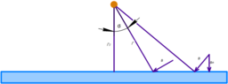
A linear conductor of length L moves at a velocity V over a fixed conductive plate at a distance R0. Current flows through the conductor, the direction of movement of the conductor is perpendicular to the direction of current in it. Find the retard force that acts on the conductor


The equation for magnetic induction of a straight wire is
##B = \mu \cdot \frac{I}{2 \cdot \pi \cdot r}##
Depending on the angle (see picture):
##B\left(\alpha\right) = \mu \cdot \frac{I}{2 \cdot \pi \cdot \frac{{r}_{0}}{\mathrm{\cos}\left(\alpha\right)}} = \mu \cdot \frac{\mathrm{\cos}\left(\alpha\right) \cdot I}{2 \cdot \pi \cdot {r}_{0}}##
To calculate the emf we need the vertical component of the magnetic induction vector:
##{B}_{N}\left(\alpha\right) = \mu \cdot \frac{\mathrm{\cos}\left(\alpha\right) \cdot I}{2 \cdot \pi \cdot {r}_{0}} \cdot \mathrm{\sin}\left(\alpha\right)##
Wire current from ##\varepsilon = B \cdot l \cdot \upsilon \cdot \mathrm{\sin}\left(\alpha\right)##:
##I = \frac{{B}_{N} \cdot l \cdot \upsilon}{R}##
where R is the resistance of a single conductor of the conductive plate, V - speed of the conductor moving over the plate.
Ampere's law for two conductors carrying current:
##F(\alpha) = \mu \cdot \frac{{I}_{1}{I}_{2}}{2 \cdot \pi \cdot r} = \mu \cdot \frac{I \cdot (\frac{\mu \cdot I \cdot \mathrm{\cos}\left(\alpha\right) \cdot \mathrm{\sin}\left(\alpha\right) \cdot l \cdot \upsilon}{2 \cdot \pi \cdot {r}_{0} \cdot R})}{2 \cdot \pi \cdot \frac{{r}_{0}}{\mathrm{\cos}\left(\alpha\right)}} = \mu^2 \cdot I^2 \cdot \mathrm{\sin}\left(\alpha\right) \cdot \mathrm{\cos}\left(\alpha\right) \cdot l \cdot \upsilon \cdot \frac{\mathrm{\cos}\left(\alpha\right)}{R \cdot 4 \cdot \pi^2 \cdot r^2}##
To obtain the total force, integrate from 0 to pi/2 (infinity):
##F = \frac{l \cdot \upsilon}{R} \cdot {\left(\frac{\mu \cdot I}{2 \cdot \pi \cdot {r}_{0}}\right)}^2 \cdot \underset{0}{\overset{\frac{\pi}{2}}{\int }}\mathrm{\sin}\left(\alpha\right)\mathrm{\cos}{\left(\alpha\right)}^2d\alpha##
##F = \frac{l \cdot \upsilon}{R} \cdot {\left(\frac{\mu \cdot I}{2 \cdot \pi \cdot {r}_{0}}\right)}^2 \cdot \left(- \frac{1}{3}\right)##
This calculation gives the total force only on the right side, the magnitude of the force to the left of the center will be equal to the right side, so everything still needs to be multiplied by 2.
How correct are these calculations?
 

Attachments

  • scheme.png
    scheme.png
    4.8 KB · Views: 32
Physics news on Phys.org
  • #2
Is this a textbook problem?
 
  • #3
icemanhv said:
Ampere's law for two conductors carrying current:
##F(\alpha) = \mu \cdot \frac{{I}_{1}{I}_{2}}{2 \cdot \pi \cdot r} = \mu \cdot \frac{I \cdot (\frac{\mu \cdot I \cdot \mathrm{\cos}\left(\alpha\right) \cdot \mathrm{\sin}\left(\alpha\right) \cdot l \cdot \upsilon}{2 \cdot \pi \cdot {r}_{0} \cdot R})}{2 \cdot \pi \cdot \frac{{r}_{0}}{\mathrm{\cos}\left(\alpha\right)}} = \mu^2 \cdot I^2 \cdot \mathrm{\sin}\left(\alpha\right) \cdot \mathrm{\cos}\left(\alpha\right) \cdot l \cdot \upsilon \cdot \frac{\mathrm{\cos}\left(\alpha\right)}{R \cdot 4 \cdot \pi^2 \cdot r^2}##
To obtain the total force, integrate from 0 to pi/2 (infinity):
##F = \frac{l \cdot \upsilon}{R} \cdot {\left(\frac{\mu \cdot I}{2 \cdot \pi \cdot {r}_{0}}\right)}^2 \cdot \underset{0}{\overset{\frac{\pi}{2}}{\int }}\mathrm{\sin}\left(\alpha\right)\mathrm{\cos}{\left(\alpha\right)}^2d\alpha##
##F = \frac{l \cdot \upsilon}{R} \cdot {\left(\frac{\mu \cdot I}{2 \cdot \pi \cdot {r}_{0}}\right)}^2 \cdot \left(- \frac{1}{3}\right)##
When going from the expression for ##F(\alpha)## to the integral, where did the ##d\alpha## come from? You can't just tack it on because it is required in the integrand. Remember that the integral is a summation. What exactly is it that you are adding?

Also, I am not sure about your approach. You are using the expression for the magnetic field due to an infinite wire but you are told that the wire has finite length ##L##. Of course, to have a current you need to have a closed loop. You also assume that the eddy currents generated in the plate are infinitely long which is stretching it. All this makes me suspect that this problem is not well-formulated.
icemanhv said:
Wire current from ##\varepsilon = B \cdot l \cdot \upsilon \cdot \mathrm{\sin}\left(\alpha\right)##:
##I = \frac{{B}_{N} \cdot l \cdot \upsilon}{R}##
where R is the resistance of a single conductor of the conductive plate, V - speed of the conductor moving over the plate.
What current ##I## and what field ##B## are these? You have already treated the conductor as carrying current ##I## (presumably established by some source) and generating field ##B## at some location in the plate. The conductor cannot be subject to a force due to the a generated by itself.

You need to rethink this problem and formulate a clear method of approach.
 
  • #4
nasu said:
Is this a textbook problem?
No, I myself am interested in finding out the acting force in order to find out whether it is worth pursuing other tasks. I would be grateful if you show examples of similar tasks
kuruman said:
When going from the expression for ##F(\alpha)## to the integral, where did the ##d\alpha## come from? You can't just tack it on because it is required in the integrand. Remember that the integral is a summation. What exactly is it that you are adding?
I consider the plate as a set of parallel conductors, a conductor that moves over the plate will create an EMF in the "conductors" of the plate. The force between the conductor and the set of conductors of the plate will be summed, Fresult = F(alpha1) + F(alpha2) + etc.
kuruman said:
You are using the expression for the magnetic field due to an infinite wire but you are told that the wire has finite length ##L##. Of course, to have a current you need to have a closed loop.
So far, to simplify the calculations, I have taken an infinite conductor with a current, I understand that this is not quite suitable for my task :rolleyes:
Perhaps I made a mistake in the formula for calculating the total force, because the elementary forces are directed between the conductors, and I did not take into account that the vectors are not collinear 🫣
kuruman said:
What current ##I## and what field ##B## are these? You have already treated the conductor as carrying current ##I## (presumably established by some source) and generating field ##B## at some location in the plate. The conductor cannot be subject to a force due to the a generated by itself.

You need to rethink this problem and formulate a clear method of approach.
Magnetic field B is the field that is created by a moving conductor carrying current. Current I is the current that is induced in the plate element
 
  • #5
icemanhv said:
I consider the plate as a set of parallel conductors, a conductor that moves over the plate will create an EMF in the "conductors" of the plate. The force between the conductor and the set of conductors of the plate will be summed, Fresult = F(alpha1) + F(alpha2) + etc.
I understand what you consider. What I am saying is that an integral is usually a summation in which you add continuously a typical mathematical expression known as the integrand. For example, when you want to find the total distance traveled by an object moving with velocity ##v(t)##, first you write a typical element that goes in the addition (the integrand) $$dx=v(t)dt$$ and then you indicate continuous summation by writing $$\int_{x_1}^{x_2}dx=\int_{t_1}^{t_2} v(t)~dt.$$ You do not write, as you have done above, $$x_{\text{result}}=x_1+x_2+~\text{etc.}$$Here, if ##\alpha## is your variable, first you need to write an expression for ##dF## which an element of force between the moving conductor and an element of "plate conductor" located at ##\alpha## as $$dF=f(\alpha)~d\alpha,$$find an algebraic expression for ##f(\alpha)## and then integrate. However, this is unlikely to yield anything useful because your model is unrealistic as I argue below.
icemanhv said:
So far, to simplify the calculations, I have taken an infinite conductor with a current, I understand that this is not quite suitable for my task :rolleyes:
Right. Maybe it simplifies the calculations but it is totally unrealistic. Your calculation is more appropriate to long parallel insulated wires arranged in a plane. If you have a continuous conducting sheet near which a magnetic field is moving, there will be eddy currents forming closed loops not long lines of current. You will be wasting your time calculating something that is not even remotely the case. Eddy current calculations are notoriously hard to perform and usually require numerical computations.
 
  • Like
Likes nasu
  • #6
icemanhv said:
No, I myself am interested in finding out the acting force in order to find out whether it is worth pursuing other tasks. I would be grateful if you show examples of similar tasks
This is what I suspected.
Unfortunately, I don't think that there is any simple model or analytical solution. The currents induced in the plate are eddy currents, not linear.
 

1. How do eddy currents create a retarding force?

Eddy currents are circular electric currents induced in a conductor by a changing magnetic field. These currents create their own magnetic field that opposes the original magnetic field, resulting in a retarding force.

2. What factors affect the strength of the retarding force due to eddy currents?

The strength of the retarding force due to eddy currents is influenced by the conductivity and thickness of the conductor, the frequency of the changing magnetic field, and the permeability of the material.

3. How can the retarding force due to eddy currents be minimized?

To reduce the impact of eddy currents, one can use materials with low conductivity, minimize the thickness of the conductor, and design the shape of the conductor to minimize the formation of circular currents.

4. What are some practical applications of understanding eddy currents and the retarding force they create?

Knowledge of eddy currents and the retarding force they produce is crucial in designing efficient transformers, motors, and generators. It is also important in the field of non-destructive testing, where eddy currents are used to detect flaws in materials.

5. Can eddy currents ever be beneficial rather than just causing a retarding force?

While eddy currents are often seen as a source of energy loss and inefficiency, they can also be harnessed for useful purposes. For example, eddy current brakes are used in some high-speed trains to provide smooth and reliable braking without physical contact.

Similar threads

  • Introductory Physics Homework Help
Replies
28
Views
319
  • Introductory Physics Homework Help
Replies
2
Views
306
  • Introductory Physics Homework Help
Replies
8
Views
400
  • Introductory Physics Homework Help
Replies
12
Views
736
  • Introductory Physics Homework Help
Replies
10
Views
265
  • Introductory Physics Homework Help
Replies
10
Views
926
  • Introductory Physics Homework Help
Replies
3
Views
336
  • Introductory Physics Homework Help
Replies
3
Views
1K
  • Introductory Physics Homework Help
Replies
4
Views
807
  • Introductory Physics Homework Help
Replies
14
Views
1K
Back
Top