- #1
NoahCygnus
- 96
- 2
- Homework Statement
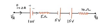
- Calculate the potential at point O in the section of the circuit shown in the diagram.
- Relevant Equations
- ##\Sigma\Delta V = 0##
In this circuit, I have to find the potential at point O. I tried using Kirchhoff's voltage law for the three open loops AOC, AOB and BOC to arrive at potential at O. According to my calculations the potential at O should be 0, but that is not the case according to the source. So I must be using Kirchhoff's voltage rule wrong. So can anyone guide me how to work this problem using KVL?
Here's my calculation:
Using KVL on AOC:
##V_1 +I_1R_1 +V_O -I_3R_3 = V_3##
Manipulating this equation to arrive at:
##I_1R_1 +V_O -I_3R_3 = V_3 - V_1## (I)
KVL on AOB:
##V_1 +I_1R_1 +V_O - I_2R_2 = V_2##
Manipulation this to arrive at:
##I_1R_1 +V_O -I_2R_2 = V_2 - V_1## (II)
KVL on BOC:
##V_2 +I_2R_2 + V_O -I_3R_3 = V_3##
Manipulating this equation to arrive at:
##I_2R_2 + V_O-I_3R_3 = V_3 - V_2## (III)
Then using the three equations above to arrive at ##V_O##
## III-(I-II) ##
Do the math and we get ##V_O=0##
But the answer in the textbook is ##V_O=[V_1/R_1 +V_2/R_2 +V_3/R_3][1/R_1 +1/R_2 +1/R_3]^-1##.
What am I doing wrong?
 ?
?