- #1
artis
- 1,481
- 976
If a current flowing within a loop is interrupted by a switch a spark occurs at some point which is a result of the built up potential across the opening switch contacts due to the stored energy in the magnetic field that was created by the flowing current.
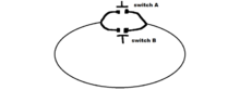
But what happens if I have a loop that has multiple switches as shown in the image attached below, where one switch is always ON (closed) while other switch/es are turned OFF (open) ?
As long as at least one switch is closed/ON the current in the loop continues to flow but what happens at the smaller wires that divide from the main loop and go to each individual switch, does a potential still form across each individual opened/OFF switch because of the current in the smaller wire that divides from the main loop?