How does Earth Ground "absorb" electric current?

In summary, the purpose of a grounded neutral is not to complete the circuit, but to protect against abnormal circumstances. In normal circumstances, current does not flow through the ground and the concept of electric potential is related to voltage but not identical. Single-wire-earth-return power circuits are rare and can cause confusion. The ground is not conductive enough for large currents to flow back to the local substation, and the resistance between a house grounding point and the substation would be too large for any significant current to flow. DC voltage is more challenging to minimize in grounding compared to AC.
  • #1
babaliaris
116
15
Untitled.jpg


This is a topic that almost no one can actually explain from what I found on the internet. This answer https://physics.stackexchange.com/q...ent-ac-require-a-complete-circuit/74999#74999 is the closest I found so far.

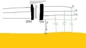
The idea is how the grounded neutral completes the circuit by closing a LOOP between the Neutral-Ground and another part of the circuit (Where the "I" current is located in the picture).

Question 1) People from my university told me that the current does not return back to the circuit but you can imagine that it "Gets Absorbed" by the earth. Is that true and how does it happen? How does a voltage drop between the Neutral and Earth, is formed so current can flow towards the earth?

Question 2) I tried to explain it by taking into consideration the capacitance that is formed between the lines and the ground. If you see it like that, then there are multiple loops between the Grounded Neutral and each phase. But is this true? If this was true then I imagine the following current flow which is not correct:
Untitled.jpg


So what is going on?
 

Attachments

  • Untitled.jpg
    Untitled.jpg
    17.2 KB · Views: 69
Engineering news on Phys.org
  • #2
The grounded neutral (MEN) is there, not to close the loop, but to protect all the insulators from destructive over-voltage.
 
  • Like
Likes cabraham, Windadct and babaliaris
  • #3
Ugh. Grounding is my least favorite topic.

First, @Baluncore 's comment is correct. The purpose of a neutral ground is not to complete the circuit, but to protect in case of abnormal circumstances.

Second, as you can see in the graphic below, current does not flow through the ground. In normal circumstances, it doesn't matter where you put the ground in the circuit. The currents, and the voltages measured by a voltmeter between any two points in the circuit, remain unchanged. The concept of electric potential at one point, is related to voltage, but is not identical to voltage, and that is probably the source of your confusion.

1668612473822.png

1668612710866.png


Third, there is such a thing as single-wire-earth-return power circuits, where the earth does complete the closed circuit. However, they are rare. You will probably never encounter one. They confuse the point you're trying to understand. So please just pretend you never heard of it. If anyone else mentions that, ignore it.

If you're still unclear, please post again.
 
  • Like
Likes babaliaris
  • #4
anorlunda said:
Third, there is such a thing as single-wire-earth-return power circuits, where the earth does complete the closed circuit. However, they are rare. You will probably never encounter one. They confuse the point you're trying to understand. So please just pretend you never heard of it. If anyone else mentions that, ignore it.
The reason why those are rare also has to do with how earth ground works.
In most places the ground is not wet and salty enough for it to conduct any large current therefore as @anorlunda said these power lines with 1 wire are rare and only for small power.

@babaliaris From what I see you have drawn everything correctly, that same connection is also used here where I live.
Normally the current flows only between the 3 phases and in some cases (single phase) back through the neutral.
The neutral is grounded and the local substation and not at the power plant, because HV power is transmitted only using phases. Then if you have a good ground connection at your house and in case your phase manages to apply it's potential to any of the grounded parts of your appliances then a current flows through the ground , but not all of that current goes back via earth to the local substation.
In fact I don't know but I would guess very little?
Most of it (since it's AC) charges and discharges the ground capacitance which is large.The reason I say that very little if any ground fault current actually makes from your home back to the local substation is because you can calculate current with Ohm's law, and if one measured the resistance between a house grounding point and the local substation the resistance would be so large in many places that no current could flow there realistically.

I'm not sure but @Baluncore or others can comment, I think with DC it would be much more challenging to lower ground fault voltage because there is no capacitive coupling to ground therefore I wonder how would a DC voltage of equal potential as AC be minimized for the same grounding as done for AC.
 
  • Like
Likes babaliaris and anorlunda
  • #5
So in other words, if I connect an ampere meter in the cable that connects the neutral and the ground I will see 0A? Even when there is a fault and the neutral has a current flowing through it?
 
  • #6
Someone once told me "Think of the ground as a large capacitor". So what if I think the circuit like this:
Untitled.png
 
  • #7
babaliaris said:
So in other words, if I connect an ampere meter in the cable that connects the neutral and the ground I will see 0A? Even when there is a fault and the neutral has a current flowing through it?
Neutral can have currents through it even under normal circumstances, that is perfectly ok.
Ground wires normally only have current in them when something goes wrong.
In that case you would see an actual current run through the wire to ground.

And yes I think you got it correctly, the ground is like a giant capacitor and the local home grounding rods are just pins that attach the house to the capacitor plate.
The other pins and the other side are at the local substation.
But here's the trick, since earth is so large and AC wires cover a long distance, even if your local substation wouldn't have a ground connection you would still have a ground current to earth if you for example attached a phase wire to ground.

The HV transmission phase wires have no direct connection to ground and yet due to their large length and surface area they form a huge capacitor towards ground. This is the major factor that causes line capacitance.
 
  • Like
Likes babaliaris
  • #8
The wires going to the infinite capacitor have resistance.
 
  • Like
Likes babaliaris
  • #9
@babaliaris Oh yes and one more thing,
@hutchphd already said it correctly, the ground is assumed as a giant almost infinite capacitor, that is because it has so much mass and area that it could store a huge amount of charge.
The thing that limits your ground current is the fact that actual soil is different from place to place and the wires/rods that go into it have finite size and resistance , so it's the "connection" and also local soil electrical properties to this "infinite capacitor" that limits how much current you can "dump" into it.
 
  • Like
Likes babaliaris and hutchphd
  • #10
That's amazing, that if the local substation is not grounded the current will still flow inside the earth from my home, even though no current will ever travel up to the local station.

I think the reason that this confuses me might be that I think of it as
Conservative Circuit: They are accurate for DC circuits, and for AC circuits at frequencies where the wavelengths of electromagnetic radiation are very large compared to the circuits
But the network system is not a Conservative Circuit since its miles large.

If I remember correctly, the reason that there is a current returning back to the - of a source and
this current has equal magnitude with the one that leaves the + of the source, it's because the circuit is conservative or something like that.

By the way, someone told me to also think of it (why the current flows towards the earth) like heat that flows towards cold areas "Naturally" without any work done by us.
 
  • #11
babaliaris said:
If I remember correctly, the reason that there is a current returning back to the - of a source and
this current has equal magnitude with the one that leaves the + of the source,
In your diagram, the power current is supplied and returned in the three 3-phase wires. The three phase system needs no neutral wire. I think you are confusing the split single-phase residential wiring with 3-phase.

This graphic may help. The red, yellow, blue curves are the power flows on the three 3-phase wires. At any point in time, they add up to zero. In other words, the power is supplied and returned on those 3 wires every instant. That's why no neutral is needed. I urge you to verify that out yourself on the graphic. Choose a few time instants and add up the three.

1668626214769.png


A small amount of leakage current might go to ground, but this is negligible compared to the current carrying the power. During abnormal cases, larger currents may go to ground, but we're focusing here on the normal case.

Yes, the ground has capacitance. It's not simple. Think of a thunderstorm and lightning. Lightning hits the ground and the electric charges eventually end up in the sky again in future clouds. That is a very complex, hard to trace, closed circuit. In fact, we normally don't think of it as a circuit at all. Aurora Borealis and Aurora Australis also bring currents to the atmosphere and the earth ground. It is even harder to trace where those charges go. Exotic and abnormal cases abound.

The point is this. Don't confuse your understanding of the simplest most normal case with exotic or abnormal cases. Focus focus focus.
 
  • #12
babaliaris said:
That's amazing, that if the local substation is not grounded the current will still flow inside the earth from my home, even though no current will ever travel up to the local station.

I think the reason that this confuses me might be that I think of it as

But the network system is not a Conservative Circuit since its miles large.

If I remember correctly, the reason that there is a current returning back to the - of a source and
this current has equal magnitude with the one that leaves the + of the source, it's because the circuit is conservative or something like that.

By the way, someone told me to also think of it (why the current flows towards the earth) like heat that flows towards cold areas "Naturally" without any work done by us.
The conservative circuit idea can really only be applied to DC. In DC you can take a car battery, take either the - or + ,but only one at a time, and stick it into ground and nothing will happen.
No Ground current will flow apart from some initial absolutely minimal almost impossible to measure tiny current blip due to the charging up of the surrounding capacitance.

Take AC , take a hot phase , even if there is no ground for thousands of miles it will still provide enough current to ground to shock you and possibly kill you if you touch it while standing on ground.
The reason for this is because it is AC, even if there is no physical current path as in a capacitor there is still charge current and since AC is either 50 or 60Hz, that means that charge current flows back n forth 50/60 times a second.

Just because you have low frequency AC doesn't mean it can't provide enough charge current given the capacitance is large.
By the way, this very idea is how back in the day people used to fool around older style single phase electricity meters. they simply took the live phase and instead of passing current back to neutral, they made a local earth connection that was good enough and used that as neutral.
Current still passed, but the meter did not turn.
 
  • Like
Likes babaliaris
  • #13
artis said:
they simply took the live phase and instead of passing current back to neutral, they made a local earth connection that was good enough and used that as neutral.
:woot: :nb)
 
  • Like
Likes davenn and babaliaris

1. How does Earth Ground absorb electric current?

Earth Ground absorbs electric current through a process called grounding. This involves connecting an electrical circuit to the ground or a large conductive object, such as a metal rod or water pipe. When an electrical current flows through the circuit, it is directed into the ground, dissipating the energy and preventing potential hazards.

2. Why is Earth Ground necessary for electrical systems?

Earth Ground is necessary for electrical systems because it provides a safe path for excess electrical energy to flow into the ground. This helps protect people and equipment from electric shocks and damage caused by power surges or lightning strikes.

3. How does Earth Ground protect against electric shocks?

Earth Ground protects against electric shocks by providing a low resistance path for excess electrical energy to flow into the ground. This reduces the amount of current that can flow through a person's body if they come into contact with a live wire, preventing serious injury or death.

4. Can Earth Ground absorb an unlimited amount of electric current?

No, Earth Ground has a limited capacity for absorbing electric current. If the amount of current exceeds the capacity of the ground connection, it can cause damage to the electrical system or create a potential safety hazard. That's why it's important to have proper grounding and to regularly check and maintain it.

5. How does Earth Ground differ from a regular electrical conductor?

Earth Ground differs from a regular electrical conductor in that it is designed to handle large amounts of electrical energy and dissipate it into the ground. It also has a lower resistance compared to regular conductors, allowing for a more efficient flow of excess current. Additionally, Earth Ground is specifically designed for safety purposes, while regular conductors are used to transmit electricity to power devices and appliances.

Similar threads

  • Electrical Engineering
Replies
19
Views
3K
  • Electrical Engineering
Replies
26
Views
1K
  • Electrical Engineering
Replies
2
Views
1K
  • Electrical Engineering
Replies
32
Views
2K
Replies
13
Views
4K
  • Electrical Engineering
Replies
1
Views
1K
  • Electrical Engineering
Replies
9
Views
1K
Replies
19
Views
628
  • Electrical Engineering
Replies
33
Views
568
  • Electrical Engineering
Replies
21
Views
1K
Back
Top