- #1
CALNNC
- 3
- 5
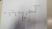
A high frequency wire dipole antenna installed at 80 feet is fed with a balanced line, at the transmitter feed point is a 1:1 balun that the balanced feeline hooks to on one side, a tuner on the other. The 1:1 balun is 12 parallel turns of #12 around a ferrite core. The input to the balun has one leg going direct to ground, grounding one side of the antenna from input to antenna wire. The other side goes to the tuner that is above ground. A 100uh coil is attached to the baluns input that does not go to ground, its function to act as a way for the ungrounded leg to have a discharge path for static buildup, and to look invisible to the RF going across it. Does it have any effect on the Murphy's Law inclination of things that are grounded that seem to attract a strike, meaning, does having that inductor installed really make a difference?