Influence of friction in pivot point(s)

In summary, the conversation revolves around calculating friction losses in a structure with 5 pivot points using deep groove ball bearings. The calculations are compared to using plain bearings and the impact on friction is discussed. The conversation also touches on factors such as pin diameter and cost considerations for different types of bearings. Ultimately, the proper way to calculate friction at joints is determined to be a multi-step process involving assumptions, load and velocity calculations, and consideration of different bearing types.
  • #1
Mech_LS24
148
16
TL;DR Summary
In a structure with 5 pivot points and provided with deep groove ball bearings. I want to calculate the losses due to friction.
Hello,

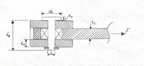
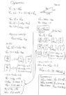
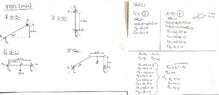
I have a structure with 5 pivot point and those are provided with deep groove ball bearings (see sketch).

Calculation for friction losses (deep grove ball bearing):
Parameters:
- Number of pivot points: 5
- Friction coefficient: 0.0010 - 0.0015 (Reference)

Total friction in the structure: 5*0.0015*100% = 0.75%

If compared to plain bearings:

Calculation for friction losses (plain bearing):
- Number of pivot points: 5
- Friction coefficient: 0.2 (worst case, Reference)

Total friction in the structure: 5*0.2*100% = 100%

I already imagined that a plain bearing has a higher impact on friction, but this amount does surprises me. Are those assumptions and calculations done in a correct manner? Or do I miss something here?

Besides, that 100% for plain bearings doesn't seem to be realistic. Does it mean the structure can't operate/move because the it can't 'overcome' the friction? 🤔
1624701044220.png
 
Engineering news on Phys.org
  • #2
Where is the pin radius or diameter specified ?

If the diameter of the pin can be reduced, the pressure will increase, but forces will remain the same, but the length of surface moved will be reduced. Thinner pins have less circumference, so less friction losses.
 
  • #3
Thanks for the reply @Baluncore .

I re-drawn the sketch and added the variables. If I take the the following dimensions and the force:
  • d1 = 10 mm
  • d2 = 16 mm
  • t1 = 4 mm
  • t2=tg = 3 mm
  • t3 = 1 mm
  • L1 = 14mm
  • L2 = 10mm
  • F = 500 N
Formulas:
  • σ = F/A (this formula is meant for the 'pressure'?)
  • M,max = (F*tg)/4 (see sketch) This formula is when the rod has a tight fit and the holes a loose fit. M,max stands for: highest bended moment.
This makes the calculations:
  • σ= 500N/(phi*10mm) = 15.9 MPa
  • M,max = (500N*3mm)/4 = 375 Nmm
But what has it to do with the friction? I can't figure it out yet... o_O

BTW, I found that latest sketch in an former school book:smile:

1624724124434.png

1624724138379.png
 

Attachments

  • 1624720719214.png
    1624720719214.png
    74.1 KB · Views: 106
  • #4
The friction coefficient of each type of bearing estimates what percentage of the load at each joint is going to become a restriction to its movement.
I would rather compare the improvement on that restriction in the following way:
Friction coefficient of ball bearing / Friction coefficient of flat bearing

Difference on cost, machining, assembly, lubrication and maintenance of each type should also be considered during the process of selection.
 
  • #5
Lnewqban said:
I would rather compare the improvement on that restriction in the following way:
Friction coefficient of ball bearing / Friction coefficient of flat bearing
You mean with flat bearing a roller bearing? What's the reason for comparing a ball bearing with a roller bearing?

Lnewqban said:
Difference on cost, machining, assembly, lubrication and maintenance of each type should also be considered during the process of selection.
More or less I try to find a 'general' influence of friction in a structure. Currently I am not able to make a 'simple' calculation for that. When having a feeling about this friction I can cover this is my design. Do you have some references for this?
 
  • #6
It's a bit confusing for me now to be honest. @Baluncore pointed me on the diameters and how pressure can be a factor on that. On the other side, friction coefficient ball bearing / Friction coefficient flat bearing. I can't imagine the factor of friction currently.

Did I start in the beginning already in the wrong way?
 
  • #7
Mech_LS24 said:
You mean with flat bearing a roller bearing? What's the reason for comparing a ball bearing with a roller bearing?More or less I try to find a 'general' influence of friction in a structure. Currently I am not able to make a 'simple' calculation for that. When having a feeling about this friction I can cover this is my design. Do you have some references for this?
No, comparing friction from ball bearing and flat bearing, which are the two types mentioned in your first post.
Once you calculate the force each joint is supporting, you can calculate its friction from the coefficients you have obtained for each specific type of bearing.
 
  • #8
Lnewqban said:
No, comparing friction from ball bearing and flat bearing, which are the two types mentioned in your first post.
I already calculated that friction coefficients, right?

Mech_LS24 said:
Summary:: In a structure with 5 pivot points and provided with deep groove ball bearings. I want to calculate the losses due to friction.

Total friction in the structure: 5*0.0015*100% = 0.75%

Mech_LS24 said:
Summary:: In a structure with 5 pivot points and provided with deep groove ball bearings. I want to calculate the losses due to friction.

Total friction in the structure: 5*0.2*100% = 100%
As above, 0.75 percent for roll bearing and 100% on flat bearing. The percentages divided by 5 tells the friction for each joint.

If every joint (assumption) should handle 40 N, the desired force needed should be at least 40.06 N (0.15% added to the 40 N)? So a flat bearing should be considered with 80 N (100% above)?
 
  • #9
Again, in my opinion, that is not the proper way to calculate friction at the joints of a mechanism.
 
  • #10
Lnewqban said:
Again, in my opinion, that is not the proper way to calculate friction at the joints of a mechanism.
What should be the proper way to calculate friction at joints? I am sorry, but I can't follow you at this point...
 
  • #11
Calculating friction for your linkage is a multi-step process. There is more than one way to do it. This is how I would attack the problem:

1) Assume an angular velocity at the input.
2) Calculate the load and angular velocity at each joint.
3) Calculate the friction torque at each joint. If you are using rolling element joint bearings, the SKF bearing catalog tells how to calculate that torque: https://www.skf.com/binaries/pub12/...ngs---17000_1-EN_tcm_12-121486.pdf#cid-121486. Start on page 132.
4) Reflect the friction torque for each joint back to the input. This might require a separate FBD for each link, starting with the link farthest from the input.
5) Sum those torques at the input. That's your total friction torque.

Note that friction torque for rolling bearings is not a simple number. This figure, from the SKF Rolling Bearing catalog, shows why:
Bearing friction.jpg

Other types of bearings have different curves.
 
  • Like
Likes Mech_LS24, Baluncore and Lnewqban
  • #12
Mech_LS24 said:
What should be the proper way to calculate friction at joints? I am sorry, but I can't follow you at this point...
Sorry.
It is important to see the difference between an estimated coefficient of friction and the resistive force from
That applies to surfaces having relative movement to each other, flat or circular, and holding some loads perpendicularly to those surfaces.
 
  • #13
A hard steel pin, resting in jewelled bearings, is used to minimise friction in instruments and clocks. The radius of the contact is small, so surface velocity is low and friction is minimised. But the mass and forces that can be supported are very limited.

A lubricated sleeve bearing can carry the greatest loads for low RPM shafts. I think that may be what you are describing as a “flat bearing”.

Rolling contacts, such as ball and roller bearings, are more bulky for the same load, but have much lower friction. The selection of the rolling bearing with the smallest radius, that is able to support the load will minimise the friction losses.

The pre-load forces on bearings, that are used to minimise lateral movement, must be added to the load forces in calculation of frictional losses.
 
  • Like
Likes Mech_LS24
  • #14
Thanks @jrmichler , @Lnewqban @Baluncore ,

jrmichler said:
This is how I would attack the problem:
I will dive again into it by following your steps. Updates will be posted :)
 
  • Like
Likes jrmichler and Lnewqban
  • #15
Energy method should be easier to calculate:

Steps 1-3: Same as in Post #11
Step 4: Calculate the power (torque X angular velocity) at each joint
Step 5: Sum the power for all joints
Step 6: Divide the total power by input angular velocity to get input torque.
 
  • #16
I have started with the calculation but I got stuck at finding the angular velocity for each joint. I am staring at this problem for a long time now, but I just can't figure out how to find Velocity at point C (see sketch). I have found the velocity at point B but how to bring this to point C?

Why am I missing?

1624906511641.png
 
  • #17
Start by searching (and studying) four bar linkage and linkage degrees of freedom. Your linkage has more than four bars, but study four bar linkages first. Your linkage, as sketched, also has too many degrees of freedom to solve.

When I once designed a four bar linkage in the real world, I used an iterative numerical method, and programmed in Matlab. I could have used a spreadsheet, but wanted to simulate a full rotation, while calculating velocity and acceleration for the entire rotation. I calculated successive positions, then velocities from differences in position, and accelerations from differences in velocities.
 
  • Like
Likes Mech_LS24
  • #18
It becomes obvious when I place the coordinate origin at the point A, that without a further constraint there is no static solution.
Looking at your diagram I see the dashed diagonal line AC of length (75). Is that a suggested start point when modelling the rotational collapse about A, or is the direction of vector AB fixed somehow?
jrmichler said:
When I once designed a four bar linkage in the real world, I used an iterative numerical method, and programmed in Matlab.
When I once modeled a linkage, I used vectors and coordinate geometry, with complex numbers. Meanwhile, "the engineer" used a spreadsheet with plenty of trigonometric functions.
Our solutions did not agree. It took a lot of searching to find his one mistake, with the sign of a sine().
 
  • Like
Likes Mech_LS24
  • #19
Baluncore said:
Looking at your diagram I see the dashed diagonal line AC of length (75). Is that a suggested start point when modelling the rotational collapse about A, or is the direction of vector AB fixed somehow?
I thought this dimension was needed because it's the distance (radius) from point A to C. All the other dimensions towards the point could be founded by the dimensions of the linkages
 
  • #20
Mech_LS24 said:
All the other dimensions towards the point could be founded by the dimensions of the linkages
What prevents the entire mechanism from collapsing, by rotation about point A ?
 
  • #21
Baluncore said:
What prevents the entire mechanism from collapsing, by rotation about point A ?
Nothing prevents the mechanism from collapsing, probably an extra 'fixed' point at B should be added?
 
  • #22
Dear @jrmichler , is this what you meant? How can friction be added to this?

1625165067726.png

1625165115780.png


1625165081145.png
 
  • #23
The angular velocity of each bearing is the difference between the angular velocities of the two links that are joined by that bearing. Now that you know the angular velocity of each bearing, along with load on each bearing, you can calculate the friction torque and power for each bearing.

Real world simplifying assumption: Normally external forces on a linkage are much larger than gravity and inertial forces on the links. When that is the case, simplify by assuming massless links.
 
  • Like
Likes Mech_LS24
  • #24
As I understand it, the work done overcoming friction is; θ·π·d·F·μ
where d is the diameter of the bearing pin, sleeve or ball race;
the distance moved is the angular change, θ, multiplied by π·d;
the force, F, is the load on the bearing;
and the friction coefficient is μ.
Notice that thinner pins offer less friction.
 
  • Like
Likes Mech_LS24
  • #25
jrmichler said:
The angular velocity of each bearing is the difference between the angular velocities of the two links that are joined by that bearing.
So below (figure 1) is the case right? The angular velocity at the 'fixed' support points (A & B) are the same as the angular velocities between BC and AB? Otherwise I interpret you wrong.

jrmichler said:
Now that you know the angular velocity of each bearing, along with load on each bearing, you can calculate the friction torque and power for each bearing.
The loads aren't known yet? I think I should add an external force for that? Probably a load vertical (downwards) at point B?
1625305021476.png
 
  • #26
The angular velocity at Point A is the difference between the angular velocity of link AB and the ground link AD. The ground link AD is the fourth link of your four bar linkage.

If you have no external loads, then your loads are the weights of the links.
 
  • #27
jrmichler said:
The ground link AD is the fourth link of your four bar linkage.
The ground link (AD) is an 0-rod? It doesn't have a function in this structure I thought.

The velocities at Va and Vb are both 0, so the is velocity in rod AD in total is 0 as well. This makes the angular velocity at point A, 6-0 = 6 rad/s. Same for point D.
 
  • #28
I tried to calculate the forces for each point, unfortunately I do something wrong...

For the force at point B and C I did the calculation with on a kinematic manner. After having the forces at point B and C I calculated the forces at point A and D by a normal FBD on the whole structure. The moment-sum gives me the force Ay which is 22.86 N. I checked it with a FBD for rod AB, but the force Ay should be 191 N?? o_O o_O

1625329028990.png


1625329047156.png

1625329055685.png
 
  • #29
Hi @jrmichler , do you see any chance in the coming days help me through this process above? I am eager to dive into it :)

Thanks
 
  • #30
I found your calculations hard to follow, so start over. Start by showing an FBD of link BC with the X and Y force components clearly shown, along with the resultant forces. Like the sketch below, except with the dimensions, forces, and angles labelled. Do the static calculations, with separate FBDs, for all three links.
FBD.jpg

It looks like you are trying to include the effects of acceleration. If so, the next step is to calculate the acceleration of each link, and show those accelerations on a separate diagram of the entire linkage, along with the mass and length of each link. Then calculate the acceleration forces and moments of each link, with separate FBDs for each link.

Now you can sum the static and dynamic forces on each link, and show those forces on a third set of three FBDs. It's a lot of sketches - nine link FBDs plus a diagram of the complete linkage. But it will be easy to follow, and easy for you to check your work.
 
  • Like
Likes Mech_LS24
  • #31
Thanks @jrmichler , really appreciate your help. I am working on your last comment, expect coming back to you tomorrow.
 
  • #32
I think I got the results. In summary (pictures are attached):

Forces are:
Fa = 125 N
Fb = 125 N
Fc = 125 N
Fd = 125 N

Angular velocities:
Wd = 6 RAD/s
Wc = 4,38 RAD/s
Wb = 4,38 RAD/s
Wa = 6 RAD/s

Do these results/calculations seems correct? Or did I miss something?

Could you help me on my way to calculate the friction at each point? :)
 

Attachments

  • v5.89_fbd_static.jpg
    v5.89_fbd_static.jpg
    19.3 KB · Views: 110
  • v5.89_dyn_fbd.jpg
    v5.89_dyn_fbd.jpg
    21.3 KB · Views: 92
  • v5.89_dyn_fbd_02.jpg
    v5.89_dyn_fbd_02.jpg
    17.2 KB · Views: 96
  • v5.89_calc_static_01.jpg
    v5.89_calc_static_01.jpg
    28.5 KB · Views: 94
  • v5.89_dyn_calc.jpg
    v5.89_dyn_calc.jpg
    37.4 KB · Views: 89
  • v5.89_calc_results.jpg
    v5.89_calc_results.jpg
    35.4 KB · Views: 101
  • #33
Numbers on the FBD's please. It's too much switching back and forth without them. The easier you make it for somebody else to follow, the easier it is to check your own work. And those other people are more willing to look into it.
 
  • Like
Likes Mech_LS24
  • #34
Sorry, I thought you didn't prefer the numbers as you said
jrmichler said:
Like the sketch below, except with the dimensions, forces, and angles labelled.

I have modified the sketches and add the numbers on it. Like to hear if it makes sense:smile:

EDIT: I see the pictures aren't sharp if you download them. Strange, because before attached them, they are pretty nice, even when the zoom function is used...
 

Attachments

  • FBD_calc_dyn.jpg
    FBD_calc_dyn.jpg
    42.9 KB · Views: 96
  • FBD_dyn.jpg
    FBD_dyn.jpg
    23.2 KB · Views: 87
  • FBD_static_calc.jpg
    FBD_static_calc.jpg
    24.6 KB · Views: 94
  • #35
https://ibb.co/SNdtmdg

https://ibb.co/MSxvNPz

https://ibb.co/6DD96S7This works better
 

Similar threads

  • Introductory Physics Homework Help
Replies
10
Views
2K
  • Introductory Physics Homework Help
Replies
6
Views
2K
  • Introductory Physics Homework Help
Replies
13
Views
3K
  • Mechanical Engineering
Replies
1
Views
3K
Replies
1
Views
1K
Replies
31
Views
1K
Replies
2
Views
2K
  • Mechanical Engineering
Replies
2
Views
2K
Replies
1
Views
2K
  • Introductory Physics Homework Help
Replies
6
Views
1K
Back
Top