Input and Output Impedance of circuit

In summary: Ro.When you decide Zout you remove Rload. This is how my examiner said.The output impedance of the first amplifier is affected by the input impedance of the second amplifier, but that effect does not change Zout1. What it does affect is the impedance at the node which is the connection of the collector of the bipolar transistor and the gate of the FET.
  • #1
David331
31
1
Homework Statement
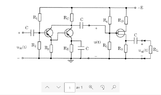
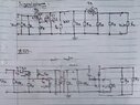
Determine the outimpedance of the first amplifier stage and the inimpedance of the second amplifier stage.
Relevant Equations
KCL, KVL, ohms law etc
Hi, I have a circuit with 3 transistors I want to rewrite to a small signal model. When multiple transistors are in the circuit I get confused how to do it. This is the signal model and small signal model I have. Is it wrong?
 

Attachments

  • 2021-12-07 (11).png
    2021-12-07 (11).png
    10.4 KB · Views: 102
  • ellära 5.2.jpg
    ellära 5.2.jpg
    75.7 KB · Views: 96
Physics news on Phys.org
  • #2
Two similar threads merged into one
Hi, I have a question regarding a transistorscircuit. I have drawn the small signal model of the circuit in the first picture, with capacitors replaced with short-circuit and grounded "-E". Furthermore, this simplified small signal model, with 1/g0, h22, h12 neglected. So, for this circuit is the outimpedance of amplifier stage 1, Zout1, Rc and the inimpedance for the second amplifier stage, Zin2, R4//R5? Or does for example the second amplifier stage somehow affect Zout1?
2021-12-07 (11).png

ellära 5.3.jpg
 
  • #4
Of course, but I cannot find the particular thing I search for: how amplifier 1 affects Zin2 and vice versa. Because if I for example only had the second amplifier I know that the inimpedance is R4//R5...
 
  • #5
David331 said:
Or does for example the second amplifier stage somehow affect Zout1?
In this case, I think it's better to think of it as the input impedance of the 2nd stage loads the output drive of the first stage.
 
  • Like
Likes Tom.G
  • #6
berkeman said:
In this case, I think it's better to think of it as the input impedance of the 2nd stage loads the output drive of the first stage.
Oh, so Zin2=Rload for amplifier 1? Because in my notes I have that Rload does not affect the outputimpedance. When you decide Zout you remove Rload. This is how my examiner said. Have I understood it wrong or?
 
  • #7
The input impedance of the second amplifier loads the output impedance of the first amplifier, but that effect does not change Zout1. What it does affect is the impedance at the node which is the connection of the collector of the bipolar transistor and the gate of the FET. If you're still having trouble understanding something, please explain in detail.
 
  • #8
Thanks for clarifying. I only have one more question. This is atleast how I have understood it, correct me if I am wrong.

When I calculated U between amplifier 1 and 2 I had the input impedance from amplifier 2 in my calculations. The inimpedance of the FET is infinity (given in the assignment), therefore no current from amplifier 1 flows through the FET transistor. If I call the current through U Ic, then U=-Ic*(Rc//R4//R5) and Ic is the collector current from both BJT-transistors.

Furthermore, U is also (by using KVL): U=Ugs+gmUgs(R3//RL).
 
  • #9
I believe you are in Sweden, so U is a voltage; is this so? If U is the voltage at the node which is connected to the collector of the BJT and the gate of the FET, then what current are you referring to when you say "the current through U"? It would be helpful if you posted a schematic with the nodes labeled and currents shown as arrows where they flow.

So, I don't see a question in your last post. What is your question?
 
  • #10
Yes, U is a voltage. I was referring to the scheamtic above, but I can show an updated one, I should have been more clear (in red the currents are IB1, IB2, IC). Furthermore, I can show you what current I have calculated so you know what I mean. My question was if my reasoning in the message prior was correct.
ellära 5.5.jpg

ellära 5.6a.jpg
 
  • #11
Your two expressions for U in post #8 are correct.
 
  • #12
Oh okay, then I know I have thought a bit correct. Thanks for the help, I really appreciate it.
 
  • Like
Likes berkeman
  • #13
David331 said:
Of course, but I cannot find the particular thing I search for: how amplifier 1 affects Zin2 and vice versa. Because if I for example only had the second amplifier I know that the inimpedance is R4//R5...

It affects it by simply circuit analysis.

The hard part is knowing what the transistor "input impedance" is. Typically there are memorized once you learn them - for a bipolar base input from a Hybrid pi model it's Rb + (Rpi + Re) * (Beta + 1). A common range of values is 1K-10K in practice: Rb is typically 10 ohms and Rpi typically 100-500 ohms and Re is a few ohms. Assuming a beta of 100, and you get 1K-10K roughly.

This become a "load resistance" of the rest of the input circuit which is all just Freshman circuit analysis then.

The same can be done for the output impedance. The output of a bipolar collector is dominated by Ro which is usually 100K-10M. This is then a "source Norton resistance" for the rest of the output circuit. Say you have a 50 ohm out in "parallel" with this out: well, 50 will dominate that exactly as desired. It's only a complication if your load impedance is with 10x of Ro and then you have to resort to analysis in more detail.

This same analysis can be used for how Stage 1 affects Stage 2 - you have a Norton with some high resistance connected with the input load/impedance of the next stage. Because Ro is generally larger than the input impedance, you have the luxury plenty of control by passives between the stages.

The painful part is DC biasing (all of the above is small signal AC). That's when you end up with interstage isolation capacitors. But at an IC level, that's not an option so you tend to do an explicit analysis of the interstage impedance matching without them combined with assuring DC bias all in the same analysis. This you'll do by hand but finish up with SPICE.
 

1. What is input impedance?

Input impedance is a measure of the resistance that a circuit presents to the input signal. It is the ratio of the voltage applied to the input of the circuit to the resulting current. It is typically measured in ohms.

2. What is output impedance?

Output impedance is a measure of the resistance that a circuit presents to the output signal. It is the ratio of the voltage at the output of the circuit to the resulting current. It is also typically measured in ohms.

3. Why is input impedance important?

Input impedance is important because it determines how much of the input signal is actually passed through the circuit. A high input impedance allows for more of the input signal to be passed through, while a low input impedance can cause the signal to be attenuated or distorted.

4. How does output impedance affect circuit performance?

Output impedance affects circuit performance by determining how well the circuit can deliver its output signal to the load. A high output impedance can cause the signal to be attenuated or distorted, while a low output impedance allows for better delivery of the signal to the load.

5. How can input and output impedance be matched?

Input and output impedance can be matched by using impedance matching techniques, such as using a buffer or amplifier between the circuit and the load. These techniques help to minimize the mismatch between the impedance of the circuit and the impedance of the load, resulting in better signal transmission and performance.

Similar threads

  • Engineering and Comp Sci Homework Help
Replies
2
Views
2K
  • Engineering and Comp Sci Homework Help
Replies
1
Views
255
  • Engineering and Comp Sci Homework Help
Replies
4
Views
2K
  • Engineering and Comp Sci Homework Help
Replies
20
Views
2K
  • Engineering and Comp Sci Homework Help
Replies
8
Views
1K
  • Engineering and Comp Sci Homework Help
Replies
4
Views
2K
  • Engineering and Comp Sci Homework Help
Replies
4
Views
1K
  • Engineering and Comp Sci Homework Help
Replies
34
Views
2K
  • Engineering and Comp Sci Homework Help
Replies
18
Views
2K
  • Engineering and Comp Sci Homework Help
Replies
4
Views
574
Back
Top