Inverting Op-amp signals and Sawtooth waveform generation

In summary: Okay, that's fair. The quote of mine that you used was agreeing with the catch by @Joshy about the incorrect connection of the 2nd opamp. The question about the inversion or whatever of the signal was in a different...In summary, the question wanted a sawtooth wave form that ranges from 0v – 5v, and the circuit created by the expert is close, but the second op-amp "flipped" the wave form.
  • #36
bob012345 said:
Well, here it is with the LT1635. I could not get to 5V because of the limitations of the op amp I believe. I had to add the capacitor also. I tweaked the resistors further but I think it is not in the spirit of the exercise. Looking at the literature, this class of op amps has a lot of sophisticated uses and using it for a simple problem such as this I think is overkill. Still, it's fun to try.

Also, I'm working on a completely different approach so please don't spill the beans just yet.
Thanks.

View attachment 286620View attachment 286622
Yes. "Rail-to Rail" is always a lie. Those saturation characteristics graphs are one of the most important parts of the data sheet for a part like this. For a high impedance load you should be able to get within <0.1V or so if you're careful (i.e. don't make it source much current).

I'm not sure the exercise wants it to get to 5V. That would be the peak voltage for lots of harmonics, but with only 4 I think the top will be rounded off below that.

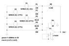
That cap isn't necessary if you choose the right resistor values. You seem to have missed the point about using a part with a built in reference to make the offset. The circuit below does this job with a single power supply, 1 IC and 7 resistors (although in the real world, I'd add a couple of caps too).

Tri_210726-1_sch480.jpg
 
Physics news on Phys.org
  • #37
bob012345 said:
Also, I'm working on a completely different approach so please don't spill the beans just yet.
Do you mean the one with a 555 timer and a current source? That would be the standard approach for sawtooth generation. Or just buy a SMPS PWM IC and only use the ramp generator in it.
 
  • #38
Averagesupernova said:
I just want to add to this thread that I wish I had gotten to know spice a lot sooner than I did. Anyone who tinkers with electronics should try it. Nothing to be afraid of.
And no one should be afraid to ask us for help during their initial learning curve.
 
  • #39
A better version, 1 less resistor:
Tri_210726-2_sch480.jpg
 

Attachments

  • Tri_210726-2_sch480.jpg
    Tri_210726-2_sch480.jpg
    26.6 KB · Views: 98
Last edited:
  • #40
bob012345 said:
Here is my version of it. I can't get a decent, readable screenshot of the output but it goes between 0 and 5V.View attachment 286511

View attachment 286513
How did you come up with the coefficients of 10,20,30,40 and RF of 3.5?

I’ve arbitrarily used 10kohms for my RF with coefficients of 10kΩ, 13.3kΩ, 20kΩ and 40kΩ which should give me gains of 1.25, 2.5, 3.75 and 5.

I was hoping as there are 4 inputs at 5volts each that 5/4=1.25 and multiples of, would give a smoother wave form. However not quite the case.
wave2.png
 
  • #41
Callum Plunkett said:
How did you come up with the coefficients of 10,20,30,40 and RF of 3.5?

I’ve arbitrarily used 10kohms for my RF with coefficients of 10kΩ, 13.3kΩ, 20kΩ and 40kΩ which should give me gains of 1.25, 2.5, 3.75 and 5.

I was hoping as there are 4 inputs at 5volts each that 5/4=1.25 and multiples of, would give a smoother wave form. However not quite the case.
View attachment 286657
Are you asking why the output solution for your circuit is the equation below?
$$ V_o = -R2( \frac{V5}{R4} + \frac{V4}{R3} + \frac{V3}{R1} + \frac{V6}{R5} ) $$

Or are you asking how to choose each of those gain terms (i.e. the resistor values)?
 
  • #42
Callum Plunkett said:
How did you come up with the coefficients of 10,20,30,40 and RF of 3.5?

I’ve arbitrarily used 10kohms for my RF with coefficients of 10kΩ, 13.3kΩ, 20kΩ and 40kΩ which should give me gains of 1.25, 2.5, 3.75 and 5.

I was hoping as there are 4 inputs at 5volts each that 5/4=1.25 and multiples of, would give a smoother wave form. However not quite the case.
View attachment 286657
I just used the given formula with ratio's 1, 1/2, 1/3 and 1/4.

##ν(t) = \frac {2}{π} (sin(wt) + \frac {1}{2} sin(2wt) + \frac {1}{3} sin(3wt) + \frac {1}{4} sin(4wt) )##

Rf should have been exactly ##10k * 2/pi *1/2## which should have been 3.183k in keeping with the exercise but I did not realize that then. Here, I made it simpler using 1k for the lowest resistor. I think this is in keeping with the original exercise.

Screen Shot 2021-07-27 at 3.19.47 PM.png
 
Last edited:
  • Like
Likes Callum Plunkett and DaveE
  • #43
DaveE said:
Are you asking why the output solution for your circuit is the equation below?
$$ V_o = -R2( \frac{V5}{R4} + \frac{V4}{R3} + \frac{V3}{R1} + \frac{V6}{R5} ) $$

Or are you asking how to choose each of those gain terms (i.e. the resistor values)?
I was wondering how you came up with the gain values for each channel. But it seems I over looked the equation as mentioned by bob012345.

Cheers guys.
 
  • #44
Callum Plunkett said:
I was wondering how you came up with the gain values for each channel. But it seems I over looked the equation as mentioned by bob012345.

Cheers guys.
That's an equation you will want to be able to derive on your own. It's not that difficult with the ideal op-amp assumptions.
 
  • Like
Likes Callum Plunkett
  • #45
Callum Plunkett said:
I was hoping as there are 4 inputs at 5volts each that 5/4=1.25 and multiples of, would give a smoother wave form. However not quite the case.
This animation shows how it works. As the number of terms grows the approximation to a sawtooth wave gets better.

https://kconrad.math.uconn.edu/math1132s10/sawtooth.htmlOf course, if one is forced to use only four terms, one can get a better fit by optimizing the values as was done in some of the previous posts.
 

Similar threads

  • Engineering and Comp Sci Homework Help
Replies
34
Views
2K
  • Engineering and Comp Sci Homework Help
Replies
13
Views
2K
  • Engineering and Comp Sci Homework Help
Replies
21
Views
1K
  • Engineering and Comp Sci Homework Help
Replies
4
Views
2K
  • Engineering and Comp Sci Homework Help
Replies
6
Views
2K
  • Engineering and Comp Sci Homework Help
Replies
4
Views
2K
  • Engineering and Comp Sci Homework Help
Replies
3
Views
2K
  • Electrical Engineering
Replies
3
Views
802
  • Engineering and Comp Sci Homework Help
Replies
1
Views
1K
Replies
9
Views
4K
Back
Top