Mystery of a Tensioned Rope Split in Two Places

In summary: I'm not the only one struggling to figure this out. I'm happy to hear that there are others out there who have the same question.
  • #1
gary808
6
6
TL;DR Summary
A Stand/Sit workstation is tensioned by internal nylon ropes. When one breaks, the internal spring snaps back into a rest state. But how did one rope break in two places simultaneously?
I'm attempting to repair my Ergotron Workfit station. After taking apart, I discovered the problem. A single nylon rope split, releasing the spring's tension. Because it is past the warranty, the manufacturer is recommending I toss the whole assembly and buy a new $650 one. Doesn't seem the sensible thing to do over a $1 rope.

33-350-211-a9-1500x1000.jpg
Pic1.jpg
Pic3.jpg
Pic5.jpg
Pic6.jpg


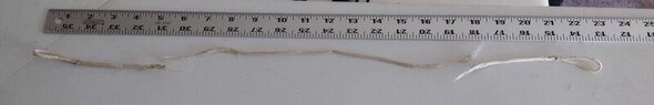
You can see from these photos, there are a total of 3 nylon ropes; one from the spring's base, one through the lower center spindle, and one longer rope just behind and to the right of the lower spindle. I'm sure that one extends up through the wheel next to the spring.

I cannot find any mechanical specs on how these 3 ropes come together and I'm hoping someone here can illustrate so I can reassemble with the new 100lbs, nylon cord.

I just can't imagine how one rope can snap in two places simultaneously. Normally once one section breaks, it relieves all the tension in the remaining cord. There'd be no second break in the same rope.
 

Attachments

  • Pic4.jpg
    Pic4.jpg
    13.8 KB · Views: 103
Engineering news on Phys.org
  • #2
I think when the first rope broke the spring put tension on the other one and it broke too.

The mechanism reminds me of a garage door spring and pulley setup where the spring counterbalances the door. This may be the case here too.

In the garage door case though usually its the spring that breaks over time and then you hear this explosive sound as it flails around breaking car windows (if there's no cable running through it) and mounting brackets.

For your mechanism it looks like the nylon rope is wrapped around the pulleys and then each end is attached to the spring.

NOTE: THE USER MANUAL SAYS THIS SECTION IS UNDER TENSION AND COULD BE HAZARDOUS.

That may be a good reason NOT to attempt to fix this without some detailed knowledge of how the mechanism works and how it is loaded and primed. I noticed in the manual there were ways to increase and decrease the tension so maybe that's how you install the rope and then increase the tension.
 
Last edited:
  • Like
Likes gary808
  • #3
Agreed about lowering the tension. I'm certain that is at least part of the factor when it comes time to reload. I'm just stuck trying to wrap my head around how these ropes interact. The lower rope that broke in two parts, feeds through the center lowest spindle. Then each end of the loops connect to the spindle just behind it.

That still leaves the LONG rope you see extending out the bottom next to the broke ropes - & - the short rope connected to the hook on the spring. Each and every rope ends in a loop which connects to something.

My only guess is that both the short and LONG ropes connect to this lower broken one. That the LONG rope loops over the wheel next to the spring and back down to the base.

Is this LONG rope a reverse tension on the spring somehow?
 
  • #4
gary808 said:
Summary: A Stand/Sit workstation is tensioned by internal nylon ropes. When one breaks, the internal spring snaps back into a rest state. But how did one rope break in two places simultaneously?

I just can't imagine how one rope can snap in two places simultaneously.
I don't have a specific answer, but here is a plausible lead-up to the problem.

That may be one continuous piece of rope but it looks like it is installed and operates as two ropes (or strands) in parallel.

For the four breaks to happen in pairs there must have been a concentration of wear at those points, likely due to the vertical position of of the work surface. For instance there were probably two preferred table heights in use.

While it is apart, look for and polish any rough spots that may contact the rope.

The manufacturers page you linked to in the OP has links to various documentation about half way down the page.

The "Recycling Guide" shows an exploded view for all parts EXCEPT the rope.

The link "CAD-2D & 3D DWG" has an Autocad file that may help, but I have nothing to read it with. There are probably free Autocad readers available but I don't have one, others here may have hints about availability.

Cheers,
Tom
 
  • Like
Likes sophiecentaur and gary808
  • #5
Yeah. Mostly I'm scratching my head trying to figure out how the ropes load the spring so that the weight of the monitor zeros out. The manufacturer (out of good legal sense) have left that information out.

I think the key to understanding, is going to be how the LONGER rope goes over the wheel at the top of the spring. Where it runs and connects from there.
 
  • #7
My experience with wire-ropes in motorcycles has been that they always fail by the area were cyclic bending happens, like next to a wrapping element that frequently rotates in both directions.

In your case, both nylon ropes seem to have been fatigued by the bottom pulley and many up and downs adjustments.
Perhaps a wire-rope surrended by plastic (like used in gym machines) could be a better option than original nylon.This may help you:
https://patentimages.storage.googleapis.com/3d/f3/0d/946b5923516afd/US8826831.pdf

US08826831-20140909-D00022.png
 
  • Like
  • Informative
  • Wow
Likes Tom.G, jedishrfu and gary808
  • #8
Okay. This is a big help! Changes my thought on how they come together. I previously thought lines 3135 & 3161 looped onto line 3132. Clearly, not correct.

Now if only I could figure out where 3135 & 3161 actually attach to. 3135 does pass under the spindle (3130). Is it possible that 3161 somehow attaches to the spindle (3130)?

I am going to reach out to Tom.G's link for additional tips. Thank you everyone!
 
  • Like
Likes berkeman, Tom.G, Lnewqban and 1 other person
  • #9
Don’t forget there is a pulley up by where the spring is attached to the frame, I suspect a rope must loop around it too.
 
  • Like
Likes Lnewqban
  • #10
That doesn't look like nylon to me, it looks like high modulus polyethylene (HMPE aka UHMWPE), trade names Dyneema, Spectra etc.) You can confirm this by heating with a flame: nylon will melt and shrink back on itself quickly and can be easily moulded when hot, dyneema is different (difficult to describe, you have to experience it really) and tends to just burn.

Also I would guess that HMPE is specified for this application beacuse it has a very low stretch: if you use nylon the table would bounce as you type. HMPE is also much stronger for a given diameter: a breaking strength of 100lb sounds inadequate for this application (the line in the picture looks about 5mm: this would have a breaking strength of about 2 tons).

To overcome the problem with wear you could use line with a braided polyester sheeth (I would not recommend aramid (Kevlar) or wire for this application as it seems to have some low radius bends).
 
  • Informative
  • Like
Likes sophiecentaur and berkeman
  • #11
@gary808 here we are almost a year later and I just had the same thing happen to mine. Were you able to figure this out?
 
  • Like
Likes sophiecentaur
  • #12
AdamDavenport said:
@gary808 here we are almost a year later and I just had the same thing happen to mine. Were you able to figure this out?
To me, it feels like planned obsolescence is at play.
Either that or they did not realize about this failure mode. If that's the case (and I hope it is) the manufacturers should be taking notes to solve the issue.
 
  • #13
I have a monitor stand by Ergotron and managed to look inside. It is much simpler that the full workstation though.

At the top of the column, there is a pulley with two different diameters.
The rope from the spring goes around the smaller diameter section, thru a slot and around the larger diameter section.
The rope then connects to the monitor mounting itself, the part that 'goes up-and-down.'

That patent link found by @Lnewqban in post 7 above looks interesting.
https://www.physicsforums.com/posts/6799067
At 47 pages if you want to understand it you probably need to print it.

Cheers,
Tom

p.s.
By the way, I had to break the latch holding the top cover to get it off. It was piece of plastic that hooks into the internal metal frame and must be bent outward to release. Totally in accessible when assembled.
The tower part has a back cover that has blind attachments that also seem to require destructive disassembly.
 
  • #14
@gary808 I managed to replace all 3 ropes and get mine reassembled, and have put together a youtube video illustrating every step. I hope this is helpful to everyone here!
 
  • Love
  • Like
  • Informative
Likes Juanda, Lnewqban and Tom.G
  • #15
AdamDavenport said:
@gary808 I managed to replace all 3 ropes and get mine reassembled, and have put together a youtube video illustrating every step. I hope this is helpful to everyone here!

This is great. Thank you for taking the time and effort.
I don't even own this piece of furniture but I found the explanation very interesting and well explained.
Besides, it's always nice seeing people trying to repair things in these times when the idea of throwing away and buying a new one is more present than ever.

(minute 4:08)
I was not familiar with the whole thing you explained about knots and spliced ropes. It feels like this knot but using only one end of the rope.
1698086323008.png


The ropes seem to be a failure point for the mechanism. I wonder if they chose the wrong option for the material by mistake or if there is another reason. From what you're seeing, it's possible to find affordable ropes of similar size that are much stronger in comparison.

(minute 4:28)
What about the splicing tool you designed? To be honest, I don't think I'll ever need it but I'm curious about how it looks within. Also, what's the wire made of?

(8:32)
The new pulley you redesigned looks much sturdier. However, don't you think the rope contacting the screw directly could be a problem in the long run? I'm somewhat involved with systems that are held together by Dyneema rope and then vibrated. The smallest dent it finds can start causing issues with the ropes. Maybe you'd put a bushing with some clearance on top of the screw so the threads don't contact the rope and also acts as somewhat of a bearing to minimize dynamic friction between the bushing and the rope.

(12:21)
Somewhat related to a previous point. Could the zip tie become an issue? Can the rope run over it or is that at an out-of-travel region of the mechanism?So again, great video. You clearly have a talent for doing and explaining these kinds of things. The choice of different colors for the ropes makes the whole explanation much easier to follow.
By the way, nice workshop. I wish I could have a similar one at some point.
 
  • #16
AdamDavenport said:
I managed to replace all 3 ropes and get mine reassembled, and have put together a youtube video illustrating every step. I hope this is helpful to everyone here!
I haven't watched the whole video. A couple of points on your eye splices:
  • Pulling the loop through the rope creates a twist in the Brummel knot. You can undo this by pulling the rope back through the knot as shown in the videos I will link below.
  • Recommendations vary for the length buried inside the core: I have never seen less than 50 times the diameter recommended but more often 60 which is what I aim for. The rope you are using looks like 4mm SK78 Dyneema (is that correct?) which implies a bury of 24cm for each end. For these short loops you haven't got room for that so I would just bury as much as I can.
  • You should taper the ends of the rope before burying them: pull out 6 of the twelve strands starting 6 braids away from the end and cut them as shown in the videos below.
There are many sources of information on rope work: the first below is a US supplier and the second a UK manufacturer.
 
  • Informative
Likes Tom.G

What happens when a tensioned rope is split in two places?

When a tensioned rope is split in two places, it results in the rope being divided into three segments. The tension in the rope causes these segments to snap back towards the points of attachment if they are fixed, potentially causing the segments to whip or flail unpredictably, depending on the amount of tension and the properties of the rope.

How does the position of the cuts affect the behavior of the rope?

The positions of the cuts significantly affect how the segments of the rope behave. If the cuts are made close to each other, the central segment will be shorter and will snap back with potentially more force due to higher tension concentrated in a smaller length. Conversely, if the cuts are far apart, the segments will be longer and might behave more like individual ropes, depending on their length and the remaining tension.

What are the safety concerns associated with cutting a tensioned rope?

Cutting a tensioned rope can be very dangerous. The primary safety concern is the unpredictable nature of the rope’s movement post-cut, as the segments can whip back with considerable force and speed, causing injuries or damage to nearby objects or people. Proper safety gear and precautions are essential to prevent accidents.

Can the material of the rope affect the outcome after it's cut?

Yes, the material of the rope significantly affects the outcome after it is cut. Different materials have varying degrees of elasticity, tensile strength, and weight, all of which influence how the rope behaves when tension is released. For instance, a nylon rope, known for its elasticity, might snap back more violently compared to a less elastic material like hemp.

What practical applications or experiments might involve intentionally cutting a tensioned rope?

Intentionally cutting a tensioned rope can be useful in various scientific experiments and practical applications. For example, in safety testing, engineers might cut tensioned ropes to study the dynamics of cable failures in bridges or elevators. It can also be used in controlled demolitions or in stunt performances to create dramatic effects, though all such activities require careful planning and safety measures.

Similar threads

  • Mechanical Engineering
Replies
3
Views
213
  • Mechanical Engineering
2
Replies
37
Views
15K
  • Introductory Physics Homework Help
Replies
9
Views
2K
  • Introductory Physics Homework Help
Replies
5
Views
34K
  • Introductory Physics Homework Help
Replies
1
Views
3K
  • Introductory Physics Homework Help
Replies
6
Views
11K
  • Introductory Physics Homework Help
Replies
6
Views
237
  • Introductory Physics Homework Help
Replies
5
Views
2K
  • Introductory Physics Homework Help
Replies
5
Views
7K
  • Introductory Physics Homework Help
Replies
2
Views
35K
Back
Top