Need a voltage divider for a capacitor source voltage

In summary: The 1k11 resistor is used to approximate 1k11111. In the simulation, the phase error is within femto-degrees and the phase plot is a mess due to floating point resolution.
  • #1
imsmooth
152
13
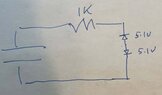
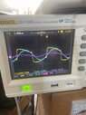
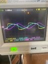
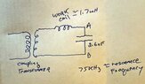
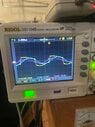
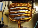
The end goal is I need to convert a sinusoidal into a square wave using a zero crossing circuit. I have a voltage that ranges from 0 to 400vrms @70kHz from a capacitor that is part of an induction heater tank circuit. My comparator has a peak differential input of +/- 35v so I need to reduce the capacitor voltage by a factor of 10 without significantly shifting the phase. I have tried using low inductance resistors as a divider but they still shift the waveform to the left. I have tried using a capacitative divider but this too shifts and distorts my voltage. I know there has to be a simple solution or how else could oscilloscopes measure these signals without altering their phase.
 
Last edited by a moderator:
  • Like
Likes AlexB23
Engineering news on Phys.org
  • #2
Welcome to PF.

Use series limiting resistors and diode clamps to reduce the max voltage seen by the comparators.
 
  • Like
Likes DaveE
  • #3
I'll give that a try. It's simple enough.
BTW, as an aside, how does an oscilloscope make a measurement without affecting the phase? I've seen the probe schematics and there is a simple resistive divider. There is a parallel capacitor. Still, there are stray inductances and capacitances that would affect phase, unless this is all relative since all measurements within a circuit would be affected by the same amount.
 
  • #4
Unknown is your source impedance, cable capacitance and comparator load Resistors.

There are plenty of options. 40 dB high pass filter > 16kHz with high impedance.

1682305206156.png
Then with a higher load R, there is less phase shift due to the large C shunt yet high impedance 10 pF thus no distortion.
1682305514416.png
.
 
  • #5
imsmooth10 said:
BTW, as an aside, how does an oscilloscope make a measurement without affecting the phase?
The high frequency divider circuit found in oscilloscopes is both a resistive divider and a capacitive divider, in parallel. The time constant of each parallel RC is the same for each and every element of the divider chain, (or ladder).

The input signal goes to the high-resistance & low-capacitance end. The low-resistance & high-capacitance end is grounded. The attenuated signal is taken from one of the taps on the chain, (or one of the legs on a ladder).
 
  • Like
  • Informative
Likes Klystron and berkeman
  • #6
High impedance probes are susceptible to ground wire noise resonance to coax. If you have a 400V sine wave and good ground reference Using my latter plot with 10 pF signal 100:1 attenuator, this is also high impedance so it must share the same ground locally to the signal, then The large cap is high impedance to line freq and becomes low Z with rising frequency. You can add 75 Ohms in series to improve coax impedance matching for EMI ingress.

Just a thought to block low and high f noise using 100:1 L andC ratios with R load for low f reject.
1682342213850.png
Not shown is some capable impedance which I assume might be CATV coax 75 ohm with F connectors and the 56K is the parallel effect of some DC bias R if needed for single supply comparator.Then the clever part is to use this with ac positive feedback = 1 and DC negative feedback to sync the oscillation to its resonant frequency of the tank with plastic cap C and heater L to boost power/efficiency.

Your induction heater values will differ and need specs.

1682343885405.png
 
Last edited:
  • #7
What software are you all using to simulate the circuit response. It seems you can put a test circuit together and analyze it pretty fast.
 
  • #9
imsmooth10 said:
What software are you all using to simulate the circuit response. It seems you can put a test circuit together and analyze it pretty fast.
I use LTspice which is free.

decade_1.png


Range_1.png
 
  • Informative
Likes berkeman
  • #10
The best tool is the one we know how to use best (as long as it does the job)

Falstad.com/circuit is more of a conceptual training device I use to show others, then I'll add parasitics to show reality. But LTspice does nice plots too.

It took me a few minutes to realize your mid-band peaking in phase error was due to truncation of 1.11k vs 1.11111K although 0.03 deg is maybe flat enough. 1% real tolerances would be 10x worse.

I once helped someone make the induction heater seek to zero phase error.
 
Last edited:
  • Like
Likes berkeman
  • #11
TonyStewart said:
It took me a few minutes to realize your mid-band peaking in phase error was due to truncation of 1.11k vs 1.11111K although 0.03 deg is maybe flat enough.
For a real 9n0 capacitor, I would use a couple of real 1n8 caps in series.
For the 1k11111 resistor, I used 1k2 // 15k, but then the phase error in the simulation become femto-degrees and the phase plot was a mess due to floating point resolution. Hence, I simulated 1k11 to show the crossover between R and C at f=1/(2Π⋅RC).
 
  • Like
Likes TonyStewart
  • #12
In theory, that works perfectly. In practice, tolerance errors arise.
 
  • #13
TonyStewart said:
In theory, that works perfectly. In practice, tolerance errors arise.
Thank you for pointing out the obvious.
In theory, there’s no difference between theory and practice. In practice, there is.
 
  • Like
Likes berkeman and TonyStewart
  • #14
It is also worth pointing out the not-so-obvious self-heating of R dividers and the breakdown voltage rating depends on length of surface creepage. (e.g. 0.25 W axial 250 V max).

High voltage bushings often just use a ceramic gap for a >=15kV voltage divider 1000:1. So for high AC voltage, C dividers are more popular and impedance in all cases must be known.
 
  • #15
Thanks for the help so far, but I'm still not making progress.

The first image is the basic schematic of the induction heater tank using a coupling transformer to drive it. The capacitor is 2.6uF and resonance is around 75kHz. The second image shows the inverter voltage (yellow) and current (blue) both in phase. At this point the tank capacitor voltage lags the current by 90 degrees (still shown in the second image). I am using a differential probe on the tank capacitor. This voltage can range from 0 to 400Vrms.

I need to measure this voltage without affecting its phase, scaling it down to under 15v at its maximum value. I tried using 10k 5W resistors connected to points A and B with two zener diodes (1N5338, 5.1v 5W) back to back to limit the voltage to +/- 5v. I got the waveform shown in 3. As you can see, the waveform is severely shifted to the left. The zener setup is shown in image 4. I am keeping the voltage low because I know the resistor is undersized for the full wattage.

I am guessing that the high resistive reactance overwhelm the capacitative reactance, so the phase angle is close to zero? I tested the resistor/zener circuit using a signal generator at 70kHz and it works there. It does not work when I connect it across the actual tank capacitor.

Anyway, my question is how can I measure the tank capacitor voltage, scaling it down, without affecting the phase angle. Again, my goal is determine the zero crossing.
 

Attachments

  • wave3.jpg
    wave3.jpg
    30 KB · Views: 64
  • wave2.jpg
    wave2.jpg
    41.1 KB · Views: 72
  • wave1.jpg
    wave1.jpg
    40.5 KB · Views: 65
  • tank.jpg
    tank.jpg
    59.2 KB · Views: 62
  • #16
Schematic omissions account for your errors.
The LC phase shift is 0 to 180 deg so is should be 90 deg at resonance with Vcap as output.
If 10K is loading your signal, then your source and transformer impedance ought to be defined along with turns ratio.

In any case, one solution is to use a large 1nF metal film (1kV) to small 100 nF ceramic (>50V) for a 100:1 reduction and no loading effect. Then the diodes are not necessary.
 
  • #17
TonyStewart said:
The best tool is the one we know how to use best (as long as it does the job)

Falstad.com/circuit is more of a conceptual training device I use to show others, then I'll add parasitics to show reality. But LTspice does nice plots too.

It took me a few minutes to realize your mid-band peaking in phase error was due to truncation of 1.11k vs 1.11111K although 0.03 deg is maybe flat enough. 1% real tolerances would be 10x worse.

I once helped someone make the induction heater seek to zero phase error.
Found a lot of sites to download LTSpice for the Mac. Are these all the same? I found this site
https://ltspice.en.softonic.com/mac?ex=DINS-635.2

Should this work?
 
  • #18
TonyStewart said:
Schematic omissions account for your errors.
The LC phase shift is 0 to 180 deg so is should be 90 deg at resonance with Vcap as output.
If 10K is loading your signal, then your source and transformer impedance ought to be defined along with turns ratio.

In any case, one solution is to use a large 1nF metal film (1kV) to small 100 nF ceramic (>50V) for a 100:1 reduction and no loading effect. Then the diodes are not necessary.
The coupling transformer is 20 turns around a toroid core. A single turn copper tube goes through the center.

Are you suggesting using a capacitative divider 1nF:100nF? I've tried one but not with those values. I'll give it a try.
 
  • #19
yes the values are important
 
  • #21
TonyStewart said:
yes the values are important

imsmooth10 said:
The coupling transformer is 20 turns around a toroid core. A single turn copper tube goes through the center.

Are you suggesting using a capacitive divider 1nF:100nF? I've tried one but not with those values. I'll give it a try.
(YES) !

What is your primary voltage and current? I believe the transformer if not impedance matching will lower the maximum power available to the coil. I'm guessing it is a battery powered mOhm massive current inverter to low inductance core. to get high voltage out ... hmm. This is high sensitive to RdsOn on primary and very high Q on secondary unless heating metal which dampens the Q.
 
  • #22
It's a 10kw inverter. 240vac in. Voltage doubler used to boost primary DC to 750vdc. Mosfets at max can take 50A. Right now I am using an algorithm on an Arduino to determine the maximum current to find resonance. Using a PLL and comparing the phase of the tank capacitor against the inverter input voltage gives a more accurate value. However, I am having the difficulty of scaling the tank capacitor voltage down to a safe value for the 15v PLL chip.
 
  • #23
TonyStewart said:
Schematic omissions account for your errors.
The LC phase shift is 0 to 180 deg so is should be 90 deg at resonance with Vcap as output.
If 10K is loading your signal, then your source and transformer impedance ought to be defined along with turns ratio.

In any case, one solution is to use a large 1nF metal film (1kV) to small 100 nF ceramic (>50V) for a 100:1 reduction and no loading effect. Then the diodes are not necessary.
So I tried the capacitor values. On a tabletop waveform generator it reduces the input by a factor of 100 as predicted. However, on the tank circuit it only reduces the capacitor voltage by a factor of 3 and the phase is shifted to the left. I would think this should work, but it does not.
 

Attachments

  • wave5.jpg
    wave5.jpg
    41 KB · Views: 61
  • #24
Where is the ground on the secondary circuit, is it terminal B of the capacitor?
 
  • #25
Thread closed briefly for Moderation...
 
  • #26
imsmooth10 said:
It's a 10kw inverter. 240vac in. Voltage doubler used to boost primary DC to 750vdc. Mosfets at max can take 50A. Right now I am using an algorithm on an Arduino to determine the maximum current to find resonance. Using a PLL and comparing the phase of the tank capacitor against the inverter input voltage gives a more accurate value. However, I am having the difficulty of scaling the tank capacitor voltage down to a safe value for the 15v PLL chip.
I guess I should have asked a few questions earlier in this thread. What is your background dealing with high voltages and SELV? Can you upload a block diagram of this whole system? (use Attach Files under the Edit window)

Where are your SELV safety boundaries, and how are you handling the groundings between the high voltage parts of this system and the SELV parts of this system that are user-accessible?

Thread re-opened provisionally depending on the OP's replies...
 
  • #27
The 15v supply uses the regular MAINS as a power source. The 240vac for the inverter voltage rails goes through an isolation transformer so there is no connection to ground. The LC tank that is driven by the inverter is coupled with a toroid transformer, so it too has no path to ground.

I've been working with high voltage for over 20 years. This is just a hobby for me.
 

Attachments

  • highpowerinverter.gif
    highpowerinverter.gif
    37.1 KB · Views: 57
  • #28
Baluncore said:
Where is the ground on the secondary circuit, is it terminal B of the capacitor?
The tank capacitor has no connection to earth ground. Voltage measurements are being made with a Tektronix differential probe.
 
  • #29
imsmooth10 said:
The tank capacitor has no connection to earth ground. Voltage measurements are being made with a Tektronix differential probe.
That is for your measurements, but how will you deliver the signal to a zero crossing comparator, without some common mode range or reference voltage?

What prevents transformer insulation or capacitor dielectric breakdown?
 
  • Like
Likes DaveE and berkeman
  • #30
The capacitor is a Celem equivalent. It is specifically made for this. 1000A/550Vrms. The coupling transformer uses heavy Lidz wire and can handle the current. Cooling fans keep the toroid core cool.

The comparator would take the differential input from the capacitor tank just like my differential probes. I can try to put a grounding connection in the middle of a balanced resistive divider. I'll put two 1meg/100k dividers in series with the ground in the center and see if that makes a difference.

What I find strange is that all of these dividers (capacitor, resistor) work on a function generator, reducing the voltage by a factor of 100. When I try it on the tank capacitor it only drops it by a factor of 3. When I tried the zener diodes they did not clamp the voltage at all. I'm missing something which is why I'm reaching out here.

The image is the coupling transformer.
 

Attachments

  • primary.jpg
    primary.jpg
    24.6 KB · Views: 57
Last edited by a moderator:
  • #31
imsmooth10 said:
I'm missing something which is why I'm reaching out here.
You are missing a solid ground on the secondary side of your circuit.
 
  • Like
Likes hutchphd
  • #32
In #4 I said "Unknown is your source impedance, cable capacitance and comparator load Resistors."

This is still true. In addition, the circuit Z(f), then for measurement errors, the choice of ground for Tek Diff probe and the entire schematic of signals, gnd. are missing. I suspect these account for measurement errors. as the 1000 pF divider should not load the 2.6 uF Cap unless there is a Vcm violation on the Diff Probe.

I see a water-cooled 0.5" copper pipe for 1 turn, but it is not shown in the schematic . As @Baluncore says, the TEK Diff probes need a solid ground = 0V reference to low impedance signals and not be floating or to some other ground. Verify that the Diff Probes give 0V on the ground and when shorted together to either test point. While monitoring the output with an antenna wire on another channel to ensure there is no crosstalk and the output remains constant. It doesn't have to be accurate, its just that your probing method must not load the output when this is done correctly. Obviously, there is enough power to fry a chicken here, so be careful about wristwatches and rings.

I admire your persistence. :biggrin: but I found it easier just to buy a 1.5kW portable induction heater plate. Now the wife uses a new gas stove.
 
  • #33
That's funny with buying a heater plate. I'm all set with the gas stove.

I made a solid ground connection and much as I thought there is no difference. The probes work fine and as you can see if a previous post image, they accurately show the 90 voltage lag on the capacitor when I put the probes across it. I get the same strange behavior with a ground connection and a resistor or capacitor divider:

I do not get 1:100 attenuation; I only get about 1:3
The signal is shifted to the left and distorted.

If anything comes of this I was playing with the LTSpice last night and I thank you for the link. When setting up the .trans command it seems that the Mac requires you to manually type in the values while the PC has a better interface. Is that correct?

Also, what is the deal with the currents going backwards unless I flip the components. It seems current flows from node 1-->2, 3-->4. The voltage source also seems to have the current going backwards from + to -.
 
  • #34
imsmooth10 said:
I made a solid ground connection and much as I thought there is no difference. The probes work fine and as you can see if a previous post image, they accurately show the 90 voltage lag on the capacitor when I put the probes across it. I get the same strange behavior with a ground connection and a resistor or capacitor divider:
Your physical circuit will need a ground connection to protect the insulators, so install a real ground connection now, tell us where it is, and keep it in place. That is also a safety issue.

You are also going to need a protective ground when you use a comparator. If, as you say, the ground makes no difference to the 3:1 problem with your prototype, then why do you resist installing the protective ground now?

I learned, long ago, not to waste time diagnosing problems without a solid ground. I cannot diagnose your 3:1 problem, without a ground and a circuit diagram showing that ground.

imsmooth10 said:
When setting up the .trans command it seems that the Mac requires you to manually type in the values while the PC has a better interface. Is that correct?
I do not use Mac so I do not know. Mac costs too much and restricts the software I can run. LTspice has the same internal functionally. There are often several ways to edit something, by using mouse clicks while holding control keys.

imsmooth10 said:
Also, what is the deal with the currents going backwards unless I flip the components.
You have discovered that the reference current direction is terminal 1 of the component. It is an old and fundamental convention that, earlier, made SPICE possible. You will need to follow, or work around it. If it is a problem, flip the component, or place a unary negative sign in the specification, or the plot window trace equation.
 
  • #35
Do you have some design specs for input and output at each interface.

If a 100:1 impedance divider operates as 3:1 then you must have crosstalk.

Without an accurate schematic and layout of all components , your problem is unsolvable.
 

Similar threads

Replies
38
Views
3K
Replies
27
Views
458
Replies
20
Views
2K
Replies
14
Views
2K
  • Electrical Engineering
Replies
22
Views
2K
Replies
3
Views
556
  • Electrical Engineering
Replies
16
Views
1K
  • Electrical Engineering
Replies
2
Views
1K
Replies
6
Views
2K
Replies
14
Views
6K
Back
Top