Understanding the Basics of VNA Measurements with an SMA Connector

In summary: Vector Network Analyzer.In summary, this person is trying to learn about electrical engineering by reading and doing. They do not have a lot of intuition yet, and are asking a question in the context of very basic physics. They are wondering what they should do with the outer connector on their VNA. The VNA is designed to analyse a network at the other end of a coaxial cable, so the outer connector is just a reference point. If you connect only the center conductor of the SNA to a piece of metal, you get a spectrum. If you connect the outer connector to something, the analysis signal will be transmitted and received on the center electrode, referenced to the outer connector.
  • #1
Thomas Rigby
22
3
TL;DR Summary
Conceptual question for intuitive understanding
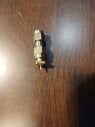
I have a VNA with an SMA connector for measuring reflection. If I connect only the center conductor of the SMA to a piece of metal, I get a spectrum. My question is, what should I be doing with the outer connector?

I am trying to learn EE by reading and doing. I don't have a lot of intuition yet, and I am asking this question in the context of very basic physics in terms of currents, voltages, conductors, etc. I don't know how to "google" this question, so I am asking humans to help me understand.
 
Engineering news on Phys.org
  • #2
The VNA is designed to analyse a network at the other end of a coaxial cable.
You have no cable, and no matching network for the wire, which is like a whip antenna.

The outer part of the SMA connector is supposed to be ground. The analysis signal is transmitted and received on the centre electrode, referenced to the outer electrode.
 
  • Like
Likes DaveE
  • #3
Thank you, I believe I understand. Since the outer connector is just a reference point, I don't need to connect it to anything, unless I have some reason for preferring a different reference.
 
  • #4
Thomas Rigby said:
Thank you, I believe I understand. Since the outer connector is just a reference point, I don't need to connect it to anything, unless I have some reason for preferring a different reference.
This is too simple, I'm afraid. If you consider the current flowing 'out' of the centre pin of the connector, equal and opposite current will be flowing 'in' to the screen / outer conductor. Its path can be back down the outer of the coax, out along an Earth plane (if that's the way it's mounted) or a path through anything else the connector is mounted to.

The DC 'reference point' you refer to is not very relevant, imo but the mean potential will depend on the ratio of the impedances of the two legs of the circuit (wire and undefined base connection).

We have slid seamlessly into how antennae are fed and the impedances they present to the feeder. How far didi you want to go?
 
  • Like
Likes DaveE
  • #5
I connect this to my NanoVNA. The reason I sent this image is to show you that there is no connection between the inner conductor and the outer conductor. My mental picture is this: a signal is transmitted out along the inner conductor, hits whatever is at the other end (in this image, nothing) and the NanoVNA looks at the reflection. No different than jiggling the end of a string, and looking at what comes back from whatever the other end of the string is attached to (possibly attached to nothing).

If my mental picture is an oversimplification, then I need to understand what I am missing.
 

Attachments

  • VNA_connector.jpg
    VNA_connector.jpg
    40.5 KB · Views: 58
  • #6
Thomas Rigby said:
My mental picture is this: a signal is transmitted out along the inner conductor,
A popular misconception. Inside a coax cable, there is equal and opposite current on the inner and back down the (inside of the) outer. At the open end, that outer current has to go somewhere. That may go down on the outside of the screen or anywhere else it may be connected to. Think of the Kirchhoff 1 Law. The sum of the currents is zero. So you can't ignore the coax screen - you have to define how it's connected before you can predict what's happening. The signal 'on the wire' is affected by the waves elsewhere.
 
  • #7
I don't attach a coax cable to the little wire. I attach a solid 14 AWG wire to it. There is no co-axial wire.
 
  • #8
Thomas Rigby said:
I connect this to my NanoVNA. The reason I sent this image is to show you that there is no connection between the inner conductor and the outer conductor. My mental picture is this: a signal is transmitted out along the inner conductor, hits whatever is at the other end (in this image, nothing) and the NanoVNA looks at the reflection. No different than jiggling the end of a string, and looking at what comes back from whatever the other end of the string is attached to (possibly attached to nothing).

If my mental picture is an oversimplification, then I need to understand what I am missing.
Thomas Rigby said:
I don't attach a coax cable to the little wire. I attach a solid 14 AWG wire to it. There is no co-axial wire.
Sorry to be blunt, but why are you experimenting with a Vector Network Analyzer if you don't understand the basics of transmission lines? IMO, you are wasting your time right now.

Instead, please learn the basics of transmission lines and then about the transfer functions of 2-port networks. Then learn the basics of S-parameter measurements, and then finally learn more (now with an adequate technical background) about how to use a VNA...

https://en.wikipedia.org/wiki/Transmission_line

https://en.wikipedia.org/wiki/Two-port_network

https://www.rfpage.com/s-parameters-in-rf-testing-simple-explanation/

https://en.wikipedia.org/wiki/Network_analyzer_(electrical)#VNA
 
Last edited:
  • Informative
  • Like
Likes DaveE and dlgoff
  • #9
OK, key point here in all electronics, which you seem to have missed. Voltages are ALWAYS measured between two points. Currents always have a return path. Granted for things like radio antennas it seems like it's just a wire, but, trust me, the guy that designed that knew and cared a lot about the ground side of that circuit. Maybe the earth, maybe the chassis of a car. There is ALWAYS something we can call ground.

The people that designed your VNA decided that it would be a lot easier for you to understand the instrument and to set up a good test if they gave you that ground in a convenient, standard, predictable way. That is the outer conductor of your connector, in this case. You'll want to learn about this and use it to create a test set up that you understand. Because the ground or return path IS THERE whether you know it or not. It is essential to what you are actually measuring. It's easy to collect garbage and think it's data. I've done a lot of that. Good test setups either require that you use a standard configuration that others have verified or that you put nearly as much work (often more) into verifying your test so that you're sure the data you get represents what you intended.
 
  • #10
OK, sorry in advance. I know this is harsh but...

Elon Musk could buy a da Vinci surgical robot, but he couldn't do anything useful with it without a lot of studying. The robot isn't enough, you also want a surgeon.

While they are cheap on eBay now, VNAs are intended to address some pretty complex EE issues. They are really easy to use incorrectly. So, it can be a great toy, and I would encourage you to play with it. However, if you really want to understand it you'll need to understand it. As @berkeman said, time to study up a bit. This isn't an entry level instrument.
 
  • Like
Likes berkeman
  • #11
berkeman said:
Sorry to be blunt, but why are you experimenting with a Vector Network Analyzer if you don't understand the basics of transmission lines? IMO, you are wasting your time right now.

Instead, please learn the basics of transmission lines and then about the transfer functions of 2-port networks. Then learn the basics of S-parameter measurements, and then finally learn more (now with an adequate technical background) about how to use a VNA...

https://en.wikipedia.org/wiki/Transmission_line

https://en.wikipedia.org/wiki/Two-port_network

https://www.rfpage.com/s-parameters-in-rf-testing-simple-explanation/

https://en.wikipedia.org/wiki/Network_analyzer_(electrical)#VNA
Transmission lines require two conductors. I am just using one conductor. But thanks for participating.
 
  • #12
DaveE said:
OK, key point here in all electronics, which you seem to have missed. Voltages are ALWAYS measured between two points. Currents always have a return path. Granted for things like radio antennas it seems like it's just a wire, but, trust me, the guy that designed that knew and cared a lot about the ground side of that circuit. Maybe the earth, maybe the chassis of a car. There is ALWAYS something we can call ground.

The people that designed your VNA decided that it would be a lot easier for you to understand the instrument and to set up a good test if they gave you that ground in a convenient, standard, predictable way. That is the outer conductor of your connector, in this case. You'll want to learn about this and use it to create a test set up that you understand. Because the ground or return path IS THERE whether you know it or not. It is essential to what you are actually measuring. It's easy to collect garbage and think it's data. I've done a lot of that. Good test setups either require that you use a standard configuration that others have verified or that you put nearly as much work (often more) into verifying your test so that you're sure the data you get represents what you intended.
I don't understand what you mean when you say "currents always have a return path". Suppose I have a two conducting spheres; one charged and one uncharged. If I then connect a single wire between them, a current will flow until the equilibrium is reached. There doesn't appear to be any "return path" here.
 
  • #13
Thomas Rigby said:
I don't understand what you mean when you say "currents always have a return path". Suppose I have a two conducting spheres; one charged and one uncharged. If I then connect a single wire between them, a current will flow until the equilibrium is reached. There doesn't appear to be any "return path" here.
That return path would be through the capacitor created when you put the two spheres in place. You could search for "Displacement Current" for the advanced level description.
 
  • #14
Thomas Rigby said:
Transmission lines require two conductors. I am just using one conductor. But thanks for participating.
That's nonsense. Last chance -- please read the reference links that I listed before posting further in this thread. You are wasting your time and ours. PM me when you are ready for this thread to be reopened. (click on my avatar and Start a Conversation to send me a PM)
 
  • Like
Likes sophiecentaur and Baluncore

1. What is a VNA?

A VNA, or Vector Network Analyzer, is a type of electronic test equipment used to measure the performance of high-frequency components, such as cables, connectors, and antennas. It measures the magnitude and phase of the signals passing through the device under test, allowing for the characterization of its electrical properties.

2. How does a VNA work?

A VNA works by sending a known signal into the device under test and measuring the response at different frequencies. It then compares the measured response to the known signal and calculates the magnitude and phase of the device's response. This process is repeated at multiple frequencies to create a frequency response plot.

3. What is an SMA connector?

An SMA (SubMiniature version A) connector is a type of RF (Radio Frequency) connector commonly used in high-frequency applications. It has a threaded interface and is designed to provide a secure and reliable connection for signals up to 18 GHz.

4. Why is an SMA connector important in VNA measurements?

An SMA connector is important in VNA measurements because it serves as the interface between the VNA and the device under test. It ensures that the signals are accurately transmitted and received, allowing for precise measurements of the device's electrical properties.

5. What are some common errors to watch out for when using an SMA connector in VNA measurements?

Some common errors to watch out for when using an SMA connector in VNA measurements include mismatched impedance, loose connections, and incorrect calibration. These errors can result in inaccurate measurements and should be avoided by carefully following the VNA's instructions and using high-quality connectors.

Similar threads

  • Electrical Engineering
Replies
16
Views
1K
  • Electrical Engineering
Replies
23
Views
3K
  • Electrical Engineering
Replies
12
Views
1K
  • Electrical Engineering
Replies
3
Views
2K
Replies
37
Views
3K
Replies
7
Views
1K
Replies
68
Views
4K
  • Electrical Engineering
Replies
17
Views
2K
Replies
13
Views
1K
Replies
33
Views
2K
Back
Top