Why is there no EMF induced in this circuit?

  • Thread starter doomer
  • Start date
  • #1
doomer
30
0
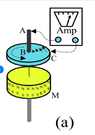
Why there is no current flow in this circuit? (simplified brushless Faraday homopolar generator)
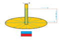
On this diagram, the copper wires are long and extend far beyond the magnetic field range and they rotate with multimeter or BT transmitter, magnet is stationary, the blue arrows symbolize hypothetical currents. I don't understand why emf is zero here. I heard that the middle wire is also cut by the magnetic field lines (because they form loops and must curl) so there is opposite current/voltage induced in the middle wire so everything cancels out, is that true?

The way I see it, the current in the middle wire should be induced perpendicularly to the wire ( - in the middle of the wire and + outside, just like in Faraday disk) so I don't understand how this could block the flow of the other currents coming from the side wires.
QUESTION.png
 
Last edited by a moderator:
Engineering news on Phys.org
  • #2
Cylindrical symmetry, if I'm reading your question correctly. The magnetic flux in each loop doesn't depend on the angle. See Faraday's Law. No change in the flux --> no induced voltage.
 
  • #3
DaveE said:
Cylindrical symmetry,...
Yes.
The plane containing the conductors is not cut by any magnetic field line.
 
  • #4
DaveE said:
Cylindrical symmetry, if I'm reading your question correctly. The magnetic flux in each loop doesn't depend on the angle. See Faraday's Law. No change in the flux --> no induced voltage.
Then why Faraday homopolar generator works? disk rotates and cut the flux lines and voltage is induced in the disk, in FHG flux does not change too.
 

Attachments

  • faraday.png
    faraday.png
    9.9 KB · Views: 40
  • #5
Baluncore said:
Yes.
The plane containing the conductors is not cut by any magnetic field line.
It is, just like in faraday disk homopolar generator?
 
  • #6
doomer said:
It is, just like in faraday disk homopolar generator?
In your diagram, the magnetic field lines that are crossed, or cut, by the wire loop, cross it again to exit, and so reverse the induced voltage, resulting in a sum zero. Where are the two wipers or brushes in your diagram?

The DC voltage produced by a homopolar generator results from the Lorentz force on the electrons, as they move with the conductive rotating disc, across the perpendicular magnetic field.
https://en.wikipedia.org/wiki/Homopolar_generator#Physics

Your loop is on edge, so there is no disc or slip ring, for a brush that is perpendicular to the field.
https://en.wikipedia.org/wiki/Homopolar_generator#Disc-type_generator
 
  • Like
Likes doomer
  • #7
Baluncore said:
In your diagram, the magnetic field lines that are crossed, or cut, by the wire loop, cross it again to exit, and so reverse the induced voltage, resulting in a sum zero. Where are the two wipers or brushes in your diagram?

The DC voltage produced by a homopolar generator results from the Lorentz force on the electrons, as they move with the conductive rotating disc, across the perpendicular magnetic field.
https://en.wikipedia.org/wiki/Homopolar_generator#Physics

Your loop is on edge, so there is no disc or slip ring, for a brush that is perpendicular to the field.
https://en.wikipedia.org/wiki/Homopolar_generator#Disc-type_generator
OK, hmmm... so In Faraday disk generator, generated current has nothing to do with the line cutting? when disk rotates, copper atoms rotate together with electrons and this is already a type of current from the perspective of the magnet so the Lorentz force kicks in and "curve" the electron flow, the Lorentz puts electron in to spiral motion and thus produces charge separation in the atoms and voltage appears, brushes collect this current from edge to the center of the disk. Is that correct?

Can current be induced If I solder wires to the disk? I've heard that not due to some 2 opposite currents blocking but I don't understand why and where they are.
 
  • #8
doomer said:
... the Lorentz force kicks in and "curve" the electron flow, the Lorentz puts electron in to spiral motion ...
The Lorentz force is orthogonal, it is not spiral nor curved. Free electrons in a vacuum will travel in a curve, spiral or helix only if they have momentum and a long free path before their next collision. The free electron cloud in a conductor has a very short free path, so they share momentum and do not curve, apart from the obvious rotation of the metal disc.

doomer said:
... and thus produces charge separation in the atoms and voltage appears ...
Sounds simple. The electron cloud is Lorentz forced to move in a straight radial direction, but only until the capacitance between the centre and circumference of the disc is charged, when the voltage gradient pushes the electrons back with an equal and opposite force. You can discharge that capacitor, and conduct the radial current, by using brushes on the disc.

doomer said:
... Can current be induced If I solder wires to the disk? ...
No. You must have two brushes, one central and one on the periphery. Otherwise, the path of the electric current will get tangled with the structure that supports the disc and the magnets that produce the field.

Electromagnetism is like two interlocked chain links. Each link passes through the hole in the other. The links represent the magnetic field and the electric current. If the links are not topologically interlocked, they are not coupled electromagnetically.
In your original diagram, you showed the lines looping in and then out of the plane of the imaginary disc. If the idea did not work as you expected, that would be the first point to examine.
 
  • Like
Likes doomer
  • #9
Baluncore said:
The Lorentz force is orthogonal, it is not spiral nor curved. Free electrons in a vacuum will travel in a curve, spiral or helix only if they have momentum and a long free path before their next collision. The free electron cloud in a conductor has a very short free path, so they share momentum and do not curve, apart from the obvious rotation of the metal disc.Sounds simple. The electron cloud is Lorentz forced to move in a straight radial direction, but only until the capacitance between the centre and circumference of the disc is charged, when the voltage gradient pushes the electrons back with an equal and opposite force. You can discharge that capacitor, and conduct the radial current, by using brushes on the disc.No. You must have two brushes, one central and one on the periphery. Otherwise, the path of the electric current will get tangled with the structure that supports the disc and the magnets that produce the field.

Electromagnetism is like two interlocked chain links. Each link passes through the hole in the other. The links represent the magnetic field and the electric current. If the links are not topologically interlocked, they are not coupled electromagnetically.
In your original diagram, you showed the lines looping in and then out of the plane of the imaginary disc. If the idea did not work as you expected, that would be the first point to examine.
Right... Lorentz force is magnetic force, so it will exert a force on a moving charge because this charge has a magnetic field around it, electrons must be moving between atoms or in free space to have a magnetic field for Lorentz interaction. A spinning copper disk (without a magnet) does not produce ions or magnetic fields, right? Sooo in Faraday homopolar generators, the disk is charged from line cutting, and Lorenz moves charges further. Is that correct?

What do you mean by tangled? My idea was to solder wires to the disk and rotate everything, including the measuring device, just like on my diagram but with a disk in place of horizontal wire, I'm using a Bluetooth transmitter, receiver, amplifier and scope, would it work?
 
  • #10
doomer said:
... electrons must be moving between atoms or in free space to have a magnetic field for Lorentz interaction.
Not just free electrons. An ion, nucleus and all, will be deflected, in a direction determined by its polarity, by an amount determined by its charge and mass.

doomer said:
What do you mean by tangled? My idea was to solder wires to the disk and rotate everything, including the measuring device, just like on my diagram but with a disk in place of horizontal wire, ...
If the connecting wire to the periphery moves with the disc, it will simply cancel the voltage generated.
You MUST HAVE BRUSHES.
If you do not use brushes, it certainly will not work.
 
  • #11
Baluncore said:
Not just free electrons. An ion, nucleus and all, will be deflected, in a direction determined by its polarity, by an amount determined by its charge and mass.If the connecting wire to the periphery moves with the disc, it will simply cancel the voltage generated.
You MUST HAVE BRUSHES.
If you do not use brushes, it certainly will not work.
Now I want to know where this canceling takes place? It's disk current vs wire current, right? if so then where the equal and opposite current is being generated? in the center wire or edge wire?
 
  • #12
doomer said:
Now I want to know where this canceling takes place? It's disk current vs wire current, right? if so then where the equal and opposite current is being generated? in the center wire or edge wire?
The radial wire. Suppose you were an electron in some metal spinning around, would you know if you were in the spinning disk or the spinning wire? There will be charge shifted radially outward in both which will generate the same radial potential difference. It's not really current cancelling, it's voltage that cancels, with no current.

I suppose if the shaft is long enough that the B-field decreases at the radial wire, you may make a little bit of a potential difference in the radial sections but that will be cancelled ultimately. The flux bending around will also interact with the axial parallel wire. Again, consider the cylindrical symmetry. You can't get emf in a loop if the net flux enclosed doesn't change. In the frame of reference of the disk, nothing is changing if you solder the wires to the disk.
 
Last edited:
  • #13
doomer said:
It's disk current vs wire current, right?
If they are in series, the current must be the same.

You ask why no EMF is induced, but it is induced, once forwards in the disc, then again equally backwards, in the wire permanently attached to the rotating disc, which moves at the same speed, through the same field.

The cancellation is of the induced voltages, voltage that was needed to drive a current.
 
  • #14
DaveE said:
The radial wire. Suppose you were an electron in some metal spinning around, would you know if you were in the spinning disk or the spinning wire? There will be charge shifted radially outward in both which will generate the same radial potential difference. It's not really current cancelling, it's voltage that cancels, with no current.

I suppose if the shaft is long enough that the B-field decreases at the radial wire, you may make a little bit of a potential difference in the radial sections but that will be cancelled ultimately. The flux bending around will also interact with the axial parallel wire. Again, consider the cylindrical symmetry. You can't get emf in a loop if the net flux enclosed doesn't change. In the frame of reference of the disk, nothing is changing if you solder the wires to the disk.
I have a problem visualizing it, it's something like this? which one is correct? A or B? for a Faraday charged disk with metal shaft or center/radial wire.
 

Attachments

  • charged disk.png
    charged disk.png
    5.7 KB · Views: 37
  • #15
Baluncore said:
If they are in series, the current must be the same.

You ask why no EMF is induced, but it is induced, once forwards in the disc, then again equally backwards, in the wire permanently attached to the rotating disc, which moves at the same speed, through the same field.

The cancellation is of the induced voltages, voltage that was needed to drive a current.
Hmm, like this? (lets say that blue arrows are voltage force vectors)
 

Attachments

  • canceling voltages.png
    canceling voltages.png
    12.4 KB · Views: 39
  • #16
doomer said:
I have a problem visualizing it, it's something like this?
You are confusing things more.
The voltage, on a moving conductor, is proportional to the radius from the axis.

The axial shaft, and/or wires parallel to the axis of rotation, (and the magnetic field), are not important as they have no voltage induced along their length.

If a radial wire rotates with the disc, it will have the same induced voltage as the disc, and so the voltages will cancel.
 
  • Like
Likes doomer
  • #17
Baluncore said:
You are confusing things more.
The voltage, on a moving conductor, is proportional to the radius from the axis.

The axial shaft, and/or wires parallel to the axis of rotation, (and the magnetic field), are not important as they have no voltage induced along their length.

If a radial wire rotates with the disc, it will have the same induced voltage as the disc, and so the voltages will cancel.
Yes I know this the pictures should represent charge distribution in more gradient look but what variant is correct A or B or none of the above?
 
  • #18
doomer said:
Hmm, like this? (lets say that blue arrows are voltage force vectors)
You make it really difficult by imagining and drawing a short bar magnet under the disc. Consider instead a parallel, vertical magnetic field from a much bigger magnet that is outside the picture.

Then the blue lines will only point sideways, not along the axis.
 
  • Like
Likes DaveE
  • #19
Baluncore said:
You make it really difficult by imagining and drawing a short bar magnet under the disc. Consider instead a parallel, vertical magnetic field from a much bigger magnet that is outside the picture.

Then the blue lines will only point sideways, not along the axis.
I think i get it now, this is the correct picture and vectors?
 

Attachments

  • canceling voltages2.png
    canceling voltages2.png
    12.8 KB · Views: 38
  • #20
doomer said:
I have a problem visualizing it, it's something like this? which one is correct? A or B? for a Faraday charged disk with metal shaft or center/radial wire.
Me too. I have no idea what those pictures mean.
 
  • #21
DaveE said:
Me too. I have no idea what those pictures mean.
The way I see it, the disc with shaft (or center wire) is charged when rotating and cutting the magnetic lines of flux, there is voltage induced and charge displacement in the disc and shaft (or center wire) just like in capacitor, red color for + and blue for - (in reality this should look more gradient like but whatever). I don't know how voltage gradient/charge displacement across disc + shaft (or middle wire) would look like, thus variant A and B.
 
  • #22
Baluncore said:
Yes.
The plane containing the conductors is not cut by any magnetic field line.

Baluncore said:
In your diagram, the magnetic field lines that are crossed, or cut, by the wire loop, cross it again to exit, and so reverse the induced voltage, resulting in a sum zero. Where are the two wipers or brushes in your diagram?
First you said that it is not cut then later you changed your mind and said that it is cut but the voltage cancels out. I like the second explanation more so now I'm trying to find the induced vectors, for the disc version and wires only version.
 
  • #23
doomer said:
I have a problem visualizing it,
If you don't have a sliding contact, then the rotation will produce a multiturn coil of wire with magnetic flux running through it. The number of turns effectively increases with ##\theta / 2\pi## as one increases theta. It comes from the topology of winding a rope (or wire ) loop onto a cylinder....you get a "winding number" from the process. Because there are no magnatic monopoles all magnetic lines of force are closed curves and the flux through stacked turns must include the number of turns.in the coil because somewhere you must cut that closed field line to add another turn unless you cut the wire with a clever contact.
 
  • #24
This is also why a DC generator has a cummutator
 
  • #25
doomer said:
I think i get it now, this is the correct picture and vectors?
Maybe this is closer. There are no voltages induced vertically. The magnetic core connects the poles outside the picture.
This is showing how it will not work, because there are no brushes and the wires rotate with the disc. If it had brushes, there would be no voltage induced in the horizontal wires.

Homopolar.png
 
  • Like
Likes DaveE and doomer
  • #26
Baluncore said:
Maybe this is closer. There are no voltages induced vertically. The magnetic core connects the poles outside the picture.
This is showing how it will not work, because there are no brushes and the wires rotate with the disc. If it had brushes, there would be no voltage induced in the horizontal wires.

View attachment 332303
Wait, the purple lines are magnetic field lines right? BUT my idea was to put wires away from the magnetic flux lines, to avoid any problems that could arise from magnetic flux lines cutting wires. I'm talking about a scenario in which magnetic field does not reach wires, magnet is under the disc and magnetism reaches the disc and half of the shaft (or middle wire) and nothing else (magnet is small).
 
  • #27
doomer said:
BUT my idea was to put wires away from the magnetic flux lines, to avoid any problems that could arise from magnetic flux lines cutting wires.
That is impossible if they are attached to, and rotate with, the disc.
If that was the case, then why did you draw the light blue arrows on the wires.
If the magnet is small and below the disc, the field will pass through the disc twice, cancelling the induced voltage.
 
  • #28
Baluncore said:
That is impossible if they are attached to, and rotate with, the disc.
If that was the case, then why did you draw the light blue arrows on the wires.
If the magnet is small and below the disc, the field will pass through the disc twice, cancelling the induced voltage.
I want to rotate disc with wires,only one magnet under the disc.
the blue arrows on the wires just symbolize canceling forces but I dont know if I understand the canceling vectors correctly, please, can you draw the canceling forces/ voltages for:
through the disc twice, cancelling the induced voltage
 
  • #29
doomer said:
Wait, the purple lines are magnetic field lines right?
You need top stop and think, why are you doing this.

Where the local bar magnet field cuts the disc, it usually goes back through again, cancelling the voltage. That wastes disc area twice.

small magnet.png
 
  • #30
Baluncore said:
You need top stop and think, why are you doing this.

Where the local bar magnet field cuts the disc, it usually goes back through again, cancelling the voltage. That wastes disc area twice.

View attachment 332304
I'm sorry but I not seeing the canceling... magnet is under the disc and in the middle of the disc and - is at the center of the disc ( - is also in the center wire) + is at the edge of the disc, polarity does not change, induced voltage/ force is radial and in one direction? ( outward or inward, depends on rotation direction or magnet polarity) the edge wire rotate but aint being cut. I know that you are right but i just can't see it, need two pictures with two pases of the disc with vectors or so something... the brushes somehow stop this canceling but the disc rotates in the brushed version in the same way...
 
  • #31
You need to stop and think.
You are still wasting our time.

State clearly if you will, or will not, use brushes.
State clearly why you are wanting to do this.

Brushes, commutators and slip rings have been the bane of electromagnetic engineering since Faraday. One big advance was when Tesla developed the induction motor. Since then, permanent magnet rotors have appeared, and that has further eliminated brushes.

The biggest homopolar generators still have brushes, and the brushes are the most difficult part of the engineering. If it was topologically possible to build a homopolar generator without brushes, some genius would have thought of it over 100 years ago.
 
  • #32
Baluncore said:
You need to stop and think.
You are still wasting our time.

State clearly if you will, or will not, use brushes.
State clearly why you are wanting to do this.

Brushes, commutators and slip rings have been the bane of electromagnetic engineering since Faraday. One big advance was when Tesla developed the induction motor. Since then, permanent magnet rotors have appeared, and that has further eliminated brushes.

The biggest homopolar generators still have brushes, and the brushes are the most difficult part of the engineering. If it was topologically possible to build a homopolar generator without brushes, some genius would have thought of it over 100 years ago.
Yes, but I want to know why brushes are necessary, if the center wire is causing trouble then why not use a ring magnet on top of copper disc and insert a mu metal pipe aka magnetic shielding in the center of such magnet to shield the center wire from magnetic field and rotate everything with load.I need pictures with vectors that show opposing forces, want to know how the brushes resolve the canceling exactly.
I've got a little advice for you:

"If you can't explain something in simple terms, you don't understand it" - Richard Feynman
 
Last edited:
  • #33
doomer said:
I've got a little advice request for you:
Fixed that for you.
 
  • Like
Likes DaveE and hutchphd
  • #34
doomer said:
u:

"If you can't explain something in simple terms, you don't understand it" - Richard Feynman
If you have a loop of wire and a loop of field to (dis)connect them one needs to cut the field line (Faraday) or cut the loop (contact). They need not be done simultaneously. Simple Chinese rings
 
  • Like
Likes berkeman
  • #35
doomer said:
I need pictures with vectors that show opposing forces, want to know how the brushes resolve the canceling exactly.
I have explained it in simple terms, but you have not understood it.

You are missing a solid and reliable foundation to electro-magnetics, and have many preconceptions, some of which are wrong. So I have no idea which way you might jump next, or what I might have to disabuse you of.

You seem to think that by making it more complex, you will understand it more easily. That is well illustrated by your placing the short bar-magnet, under the disc.

Judging by your 2D diagrams, you do not think in 3D, which is a major handicap where an inherently 3D cross-product is involved. I believe that would explain your problematic understanding of the need for brushes.
 

Similar threads

Replies
17
Views
1K
  • Electrical Engineering
Replies
14
Views
4K
  • Electrical Engineering
Replies
7
Views
214
  • Electrical Engineering
2
Replies
35
Views
3K
Replies
10
Views
2K
  • Electrical Engineering
Replies
2
Views
1K
  • General Engineering
Replies
9
Views
887
Replies
64
Views
5K
Replies
8
Views
464
  • Electrical Engineering
Replies
10
Views
4K
Back
Top