A very simple moments question

  • Thread starter Thread starter physicals
  • Start date Start date
Join the discussion
Registration is free. Ask a follow-up in this thread, or start your own.
105 replies · 14K views · last reply
physicals said:
Now that we have come to the end of the discussion, Im not sure how you end a tread, do you just stop replying, or do you click something to end it?
Just stop replying if you so desire. You cannot "click something to end it" because others may wish to continue the discussion with or without you. Only the gods, a.k.a. mentors, can close threads.
 
Physics news on Phys.org
kuruman said:
I am not sure what the system "as a whole is."
I am not sure either what @Lnewqban means by that, but it sounds like both bars + attached weight.

kuruman said:
I have considered two separate systems
But in either case Fy was the force by the wall on the horizontal bar only.
 
A.T. said:
I am not sure either what @Lnewqban means by that, but it sounds like both bars + attached weight.


But in either case Fy was the force by the wall on the horizontal bar only.
Yes, of course. The horizontal bar doesn't give a hoot about what we choose as "the system" as long as the "gallows" configuration remains unchanged. If the diagonal piece just touched the wall without being fastened and the contact were frictionless, then ##F_y## would be equal to the hanging weight.
 
kuruman said:
To answer part (b) we choose our system to be the horizontal bar only.
Is the net couple zero in this system? The couple produced by the two forces in the x-direction is zero. However, it seems that the three forces in the y-direction do not cancel to give a zero couple.
 
anuttarasammyak said:
Is the net couple zero in this system? The couple produced by the two forces in the x-direction is zero. However, it seems that the three forces in the y-direction do not cancel to give a zero couple.
Seems like you are asking the same question as @physicals,
physicals said:
... there would clearly be a net clockwise moment so the system wont be in equilibrium. Am i correct or am i missing something?
which has been answered:
A.T. said:
The arrow in the diagram just indicates the positive direction for a force component (sign convention), not the actual force direction, which is often unknown when the diagram is drawn. Since the magnitude derived for Fy is negative for L1 < L2, Fy is indeed opposite to its arrow direction for the geometry shown in the diagram.
 
I mean couple not moment. Thanks to #6 in usual case
Free-body diagram of a bracket fixed to a vertical wall (red line), with a horizontal arm carrying a downward Weight arrow, a pin with blue Force arrows at the top and bottom, and magenta -Weight and -Force arrows; labelled Anchor lever and Weight lever.

Blue forces couple and red forces couple cancel. My #16 confirms it. In the calculation of forces for horizontal bar system shown, I do not find such couple cancellation. This net zero couple seems the point of the exam in OP.
 
Last edited:
anuttarasammyak said:
I mean couple not moment.
Why does it have to be a couple? All that matters is that the net moment is zero, even if it is a triple.
 
A.T. said:
Why does it have to be a couple? All that matters is that the net moment is zero, even if it is a triple.
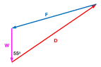
Closed force triangle with vectors labelled F in blue, D in red and W in magenta, W pointing straight down, and a 55 degree angle marked between W and D.
Having the net force equal to zero also matters, of course. The forces acting on the horizontal bar arise from three external entities, the vertical piece (or wall), the diagonal piece and the Earth. There can be no couple because with three forces, there is always an odd one out.

However, if we are allowed to move their point of application, the forces can be arranged to form a closed triangle because their vector sum is zero. The diagram on the right is the geometric solution to this question drawn to scale.
 
Vector diagram of three forces forming a triangle: magenta W points straight down, blue F points left and slightly down from the top right, red D points up and right from the bottom of W, with a 55° angle marked between W and D.|D|,|F| > |W|. The weight gravity generates larger y force. F is downward, however Free-body diagram of a bracket bolted to a vertical wall, with a horizontal arm carrying a downward Weight and labelled Anchor lever and Weight lever distances, plus Force and -Force arrows and a -Weight arrow.red force on screw is upward.”Only horizontal bar” model has something different from the original model. If D is parallel transport of the force the diagonal bar get from the wall, such a transport breaks the couple cancellation achieved in the original model.
 
Last edited:
anuttarasammyak said:
View attachment 370092|D|,|F| > |W|. The weight gravity generates larger y force. F is downward, however View attachment 370094red force on screw is upward.”Only horizontal bar” model has something different from the original model. If D is parallel transport of the force the diagonal bar get from the wall, such a transport breaks the couple cancellation achieved in the original model.

This

Free-body diagram of a bracket fixed to a vertical wall (red line) with labelled forces: Force and -Force act horizontally, -Weight acts upward, Weight acts downward at the end of a horizontal arm, with Anchor lever and Weight lever dimensions marked.

is not the same as this which is the figure found in the original post.
Diagram of a horizontal beam fixed to a vertical wall, with a strut from point P on the wall to the beam at 0.16 m from the wall, at 55° to the wall; a force F acts leftward at the beam's end, and a hemispherical bowl hangs from a hook at 0.28 m from the wall.

The answers using the free body diagram and the equations in post #13 are
Spreadsheet table listing given quantities L2 0.28 m, L1 0.16 m, W 34, θ 0.96 rad, and derived forces D 103.74, Dx 84.97, Dy 59.50, Fx 84.97, Fy -25.50, F 88.72.
 
kuruman said:
is not the same as this which is the figure found in the original post.
No, not the same in a exact sense. My post #16 based on your figure deals it.

Your case can be interpreted that we pull the horizontal bar tilt upward by the rope tagged in a mid point with greater force than gravity force W.

Are the both two models (with or without diagonal bar) to explain the OP case ?
 
Last edited:
anuttarasammyak said:
Your case can be interpreted that we pull the horizontal bar tilt upward by the rope tagged in a mid point with greater force than gravity W.
It seems you missed what post #13 shows.

I chose as system the horizontal bar only.

The physical situation says that the items exerting external forces on this system are
  1. The wall at the point of contact which could be a screw.
  2. The diagonal piece pushing from underneath up and to the right at an angle of 55o.
  3. The flower pot (assuming a massless horizontal bar) exerting its weight down at the point where the string is attached to the bar.
These external forces are represented as arrows in my post #13 diagram with force ##\mathbf F## resolved into its components.

Your drawing shows no diagonal piece and no diagonal force up and to the right. You can choose as system anything you like. However, if you remove an item from your system, and consider a reduced system, you must replace the item you removed with the force that it exerts on this reduced system. If you don't do this replacement, you have a different physical situation.
 
kuruman said:
The diagonal piece pushing from underneath up and to the right at an angle of 55o.
The blue length is important. The angle itself does not matter. Alternative orange rods are OK.
Diagram of a horizontal arm hinged to a vertical wall at point P, with a diagonal brace at 55 degrees, a force F pointing left, a hemispherical bowl hanging from the arm's end, and dimensions 0.28 m and 0.16 m marked; orange alternative brace positions are shown.

The diagonal rod tansmit not only force along it but also shearing force to the horizontal rod connected to it. In the original model it is an inner force of the rigid body which should be cancelled by another inner force so we do not have to go into the detail. We can concentrate on external forces.
 
Last edited:
anuttarasammyak said:
No, not the same in a exact sense.
Then maybe you should not refer to the model proposed in post #6 by @Lnewqban as the 'original model', because this can create confusion with the 'original post' (OP).

anuttarasammyak said:
Are the both two models (with or without diagonal bar) to explain the OP case ?
As far I can see, the two models interpret the OP differently, but should give the same result for Fx (called F in the OP).

- The model by @Lnewqban assumes sliding contact with the wall at point P and torque transmitting joints.

- The model by @kuruman assumes a torque free hinge connection to the wall at point P and at the other joints.

anuttarasammyak said:
The diagonal rod tansmit not only force along it but also shearing force
If the diagonal rod has torque free hinges at both ends (as assumed by @kuruman) it doesn't transmit a shear force (perpendicular to itself), just an axial force (along itself).
 
Last edited:
A.T. said:
As far I can see, the two models interpret the OP differently, but should give the same result for Fx (called F in the OP).
My answer #16 which is same as the exam answer has sec, however post #13 answer has tan as coefficient to $$W\frac{L_2}{L_1}$$.
 
Last edited:
anuttarasammyak said:
My answer #16 which is same as the exam answer has sec, however post #13 answer has tan as coefficient to $$W\frac{L_2}{L_1}$$
Your equation ##~L_2w=hF_x~## in #16 gives $$F_x=\frac{L_2}{h}W.$$ If you cast it in terms of the given quantities, namely ##L_1## (0.16 m) and ##\theta## (55o), you would substitute ##~h=\dfrac{L_1}{\tan\theta}~## to get $$F_x=W\left(\dfrac{L_2}{L_1}\right)\tan\theta.$$That is exactly my expression in post #13. :rolleyes:
 
Last edited:
  • Like
Likes   Reactions: A.T. and anuttarasammyak
Drawing correct FBD's seems to be a common challenge. I think a lot of the online HW sets just draw all forces in positive direction by default, which is often wrong.

Handwritten free-body diagram of a horizontal bar with points A, B and W marked, showing red arrows for the reaction forces at A, a force arrow at B and a downward load at W.
 
JLT said:
Drawing correct FBD's seems to be a common challenge. I think a lot of the online HW sets just draw all forces in positive direction by default, which is often wrong.

View attachment 370127
The symbols labeling the arrows in FBD represent magnitudes. One has to pick a direction for the tip of the arrow often without knowing beforehand if the direction is correct. This is necessary for writing down the equations and doing the algebra to get expressions for the unknown quantities. The expressions say it all. If the expression for the magnitude of a vector is negative, then its direction in the FBD must be flipped. This is not wrong because the goal of finding the magnitude and direction has been achieved.

Free-body diagram of a horizontal beam pivoted at point P, with components Fx pointing left and Fy pointing up at P, a force D at angle theta at distance L1, weight W pointing down at distance L2.
For example, I found the components of the force that you cal A and I call F using the FBD on the right. Their expressions are $$F_x=W\left(\dfrac{L_2}{L_1}\right)\tan\theta~;~~F_y=W\left(1-\frac{L_2}{L_1}\right).$$ You are arguing that this FBD is incorrect because ##F_y## should be drawn "down". I am saying, "Who cares?" In post #40 I substituted the given numbers in the equations and got
##F_x= 84.97## N; the implied plus sign means "in the same direction as drawn in the FBD."
##F_y=-25.50## N; the minus sign means "in the opposite direction as drawn in the FBD."

Did I not get the same answers as you?
 
kuruman said:
The symbols labeling the arrows in FBD represent magnitudes. One has to pick a direction for the tip of the arrow often without knowing beforehand if the direction is correct. This is necessary for writing down the equations and doing the algebra to get expressions for the unknown quantities. The expressions say it all. If the expression for the magnitude of a vector is negative, then its direction in the FBD must be flipped. This is not wrong because the goal of finding the magnitude and direction has been achieved.

View attachment 370129For example, I found the components of the force that you cal A and I call F using the FBD on the right. Their expressions are $$F_x=W\left(\dfrac{L_2}{L_1}\right)\tan\theta~;~~F_y=W\left(1-\frac{L_2}{L_1}\right).$$ You are arguing that this FBD is incorrect because ##F_y## should be drawn "down". I am saying, "Who cares?" In post #40 I substituted the given numbers in the equations and got
##F_x= 84.97## N; the implied plus sign means "in the same direction as drawn in the FBD."
##F_y=-25.50## N; the minus sign means "in the opposite direction as drawn in the FBD."

Did I not get the same answers as you?
A FBD is meant to represent real physical forces - draw forces in the direction they physically act.
Weight -s down - I also call it -w in equation ↓ in diagram = -F.

If direction cannot initially be guessed - then yes, crank through the numbers - but then fix the diagram after seeing which way everything is actually going.
 
In survey of "the only horizontal bar" model, I would like to know how we should choose the shape of the pivot in this figure to control orange colored x-force pair magnitude ? I should appreciate it if you could warn me the setting failure.

Free-body diagram of a horizontal blue beam pinned to a wall on the left and resting on a triangular pivot, with a black weight hanging on its right end, showing pink and orange force arrows and green weight arrows.
 
JLT said:
If direction cannot initially be guessed - then yes, crank through the numbers - but then fix the diagram after seeing which way everything is actually going.
What if you are deriving a general solution, not just for specific numbers? There is nothing to guess then, because some forces could point either way, depending on some free parameters.

But even for specific numbers your 'fixing the diagram' seems rather unnecessary and confusing:

You want to modify the diagram by flipping the arrows of forces that are negative in the solution? But then the diagram is no longer consistent with the computation and solution, which were based on the original diagram.

You could draw a second diagram, and present it along with a solution that contains only positive numbers, so these two are consistent. But since this offers little additional information, I would see it as optional, not required.
 
Last edited:
  • Like
Likes   Reactions: Herman Trivilino and kuruman
anuttarasammyak said:
I would like to know how we should choose the shape of the pivot in this figure to control orange colored x-force pair magnitude ?

Free-body diagram of a horizontal blue beam fixed to a wall at the left, resting on a triangular pivot, with a black weight on its right end and a grey square and semicircle on the ground beside it. Coloured arrows mark the forces on the beam.

Are these rigid bodies? Then the equal but opposed orange colored x-force pair is indeterminate: These two forces can have any magnitude (within limits of material strength and friction(?) on the "pivot").

If you want to consider deformation, then it's much more complicated and requires the material properties. And what do you mean by "to control"?

I think you should start a new thread on this.
 
The touch of theta diagonal rod to the horizontal rod generate theta force whose horizontal component decides magnitude of F. Is it obvious? Does touch angle matter? I am considering #51 for it.
 
Last edited:
anuttarasammyak said:
The touch of theta diagonal rod to the horizontal rod generate theta force whose horizontal component decides magnitude of F. Is it obvious? I am considering #51 for it.
No, it's not obvious. There is no diagonal rod or theta in post #51.
 
anuttarasammyak said:
In survey of "the only horizontal bar" model, I would like to know how we should choose the shape of the pivot in this figure to control orange colored x-force pair magnitude ? I should appreciate it if you could warn me the setting failure.
I agree with @A.T. 's suggestion
A.T. said:
I think you should start a new thread on this.
 
JLT said:
draw forces in the direction they physically act.
This is a common misconception. When you draw a force in an FBD, the direction shown only says which direction you are taking as positive. The equations written from it can then be checked against the diagram. One should not normally care, when drawing the diagram, which way it really acts.
A common approach is to pick X and Y Cartesian coordinates and express every force as its components in those directions. Doing that, it is customary to take each component as positive in the positive direction of the corresponding axis.

Friction can be tricky. Consider a mass m lying on a rough horizontal surface, acted upon by opposing horizontal forces F1, F2. Taking F1 as positive left, F2 as positive right and acceleration as positive right, what do we do with the ##\mu mg## term?
Putting aside the difficulty of not knowing whether it will slide at all (if that bothers you, consider quadratic drag instead), there are two cases for when it does.
If F2>F1 then ##F2-F1-\mu mg=ma##.
If F2<F1 then ##F1-F2-\mu mg=-ma##.
In general, ##\mu mg=|F2-F1-ma|##.
Note that the issue is not that we chose an arbitrary direction as positive for the acceleration; it is that we cannot predict which way friction acts.
 
Last edited:
As far as the jig is massless rigid body, the essential lengths are 0.28 m and 0.16 cot 55 m. The diagonal rod triangle is to give the latter length by trigonometry and plays no role in physics. If we read physics in it, we will dismay. With the latter length given, we can choose support point and angle set as we like.
 
Last edited:
anuttarasammyak said:
As far as the jig is massless rigid body, the essential lengths are 0.28 m and 0.16 cot 55 m.
For computing F only, yes. just like the solution in the OP already shows:

Marking scheme table for question 14(b): method marks for moment of force Fx, trigonometry for vertical distance, principle of moments, and F = 85 N; worked example gives moment 34 N x 0.28 m = 9.52 N m, vertical distance 0.16 m / tan(55°) = 0.112 m, and F = 9.52 N m / 0.112 m = 85 N.

anuttarasammyak said:
The diagonal rod triangle is to give the latter length by trigonometry and plays no role in physics. If we read physics in it, we will dismay.
Even though it's not asked, there is nothing wrong with computing the force in the diagonal rod too. I see no reason for dismay here.
 
For small angle the large downward force at the wall contact point and the large upward force at the diagonal rod point both go to infinity in your calculation. Is it OK?