Analog power supply output question
- Level: High School
- Thread starter Patch Cabbage
- Start date
Join the discussion
Registration is free. Ask a follow-up in this thread, or start your own.
52 replies · 7K views
Physics news on Phys.org
Patch Cabbage
- 19
- 0
It will probably just sample the line ripple and amplify it and invert it through a dropping resistor on its collector. Just a standard circuit. I wish I could find a better way of doing it since the ripple invert has to follow a variable output. Thanks.
Science Advisor
2025 Award
- 17,276
- 10,739
There are very many ways of doing it. I am interested seeing exactly how it is being done. Can you give me a link to the circuit on the web?Patch Cabbage said:It will probably just sample the line ripple and amplify it and invert it through a dropping resistor on its collector. Just a standard circuit.
Admin
- 69,806
- 25,700
Patch Cabbage said:I'm setting up an analog power supply. I have the transformer bridge and filter capacitors so far. The transformer puts out 30 volts. I am currently using two parallel power transistors and a variable resistor to set the output. It also has a meter to monitor voltage. The question is this. How do I set up a single transistor to remove whats left of the ripple after the filter capacitors. It has to vary along with the control transistors to be constant in its ripple removing. The bases of the two power transistors to the potentiometer is currently the control.
Well, it's the old GIGO principle I guess. But maybe we can still help you a bit, since this part of your circuit makes no sense to me:Patch Cabbage said:No problamo, as I have learned nothing from this thread.
The two transistors are not connected as any kind of voltage regulator. Their only function that I can see is to convert current into heat, and lower the efficiency of your unregulated power supply. Did you mean to describe some other connection of these transistors?
Science Advisor
Homework Helper
- 30,613
- 7,551
He seems to have connected the transistors as diodes. Just a more expensive solution.berkeman said:this part of your circuit makes no sense to me:
Science Advisor
2025 Award
- 17,276
- 10,739
I drew the diagram that way, as it fitted the written description. That forms a current regulator, as the resistor current is multiplied by beta, then passed to the output, and through the load.sophiecentaur said:He seems to have connected the transistors as diodes.
Science Advisor
Homework Helper
- 30,613
- 7,551
A regulator has a reference. What reference is in that circuit. (I realise that things can be hidden or inferred)Baluncore said:That forms a current regulator,
Science Advisor
Homework Helper
- 30,613
- 7,551
PF's advice is free. Learning is supposed to be an active process. The excuse is not really GIGO because a lot of the input is far from garbage.Patch Cabbage said:No problamo, as I have learned nothing from this thread.
Do your invented circuits normally work OK?
Science Advisor
Homework Helper
- 30,613
- 7,551
OK. I was looking for a voltage regulator - which is normally what one wants.
Science Advisor
Gold Member
2025 Award
- 4,605
- 4,328
But then what regulates the resistor current? If the voltage applied changes, so does the current. Just semantics, I guess. It works more like a resistor, as you described. More like a current limiter.Baluncore said:That forms a current regulator, as the resistor current is multiplied by beta, then passed to the output, and through the load.
Science Advisor
Gold Member
- 4,943
- 1,575
Hmmm. So a bit of quick math without a schematic. Suppose you want to supply 5 volts out at 30 amps. That's within the spec right? That means that since you have a max output of 40 volts, the input to the pass transistors will be at least 40 volts. However, you want 5 so there will be at least 35 volts across the pass transistors while they are conducting 30 amps if you want your supply 5 volts to a 30 amp load. That means the pass transistors need to dissipate over 1000 watts. How do you plan on getting rid of that amount of heat?Patch Cabbage said:Max 30 amps? 15a each? 0-40 on the volts.
Patch Cabbage
- 19
- 0
This should work.

Last edited by a moderator:
Science Advisor
Gold Member
- 4,943
- 1,575
If you cleaned that schematic up to make it more readable......
-
.....it still won't work.
-
.....it still won't work.
Science Advisor
Gold Member
2025 Award
- 4,605
- 4,328
I think this circuit will work the same if you replace all of the transistors with a piece of wire (OK, maybe a forward biased diode). Why would your transistors ever turn off or decrease their collector current? How would that happen?Patch Cabbage said:
Patch Cabbage
- 19
- 0
Hey, you know, that's a really good question. My first thought response would be that the variable resistor is really big, but that leads to the ripple invert is biased to be slightly on all the time. Not for sure if it will ever go down to zero. It should but it might not. Also the ripple invert is fixed and the voltage output is variable so that's not so perfect either. Then again if I had all of the answers I wouldn't have to ask someone how to do it on a physics forum. If it works, fine. If not, it's back to the old drawing board. I'm not proficient in daw and I draw still with a pen and paper and not a mouse so sorry about all the sloppy schematics.
Science Advisor
Gold Member
- 4,943
- 1,575
None of that makes any sense to me.
Science Advisor
Gold Member
2025 Award
- 4,605
- 4,328
This is one of my first real designs for money as an EE. It was drawn by hand (early 1980's) and is a #$@! sight clearer than your attempt. The reason you don't draw readable schematics is probably that you don't care enough about communication with other engineers to put in the effort required.Patch Cabbage said:I'm not proficient in daw and I draw still with a pen and paper and not a mouse so sorry about all the sloppy schematics.
This is a quick schematic sketch I drew by hand about 40 years later.

For a slightly different take on transformers, here is the lumped element model that EEs use for circuit analysis. The same material, different jargon. EEs that work with this will speak of "coupling" and "flux" in conversation (because we did actually take some physics classes); but, in my experience, they really work with "leakage inductance", "magnetizing inductance", voltages, and currents. The ideal transformer with imperfect coupling is modeled as a "T-section" shown below:
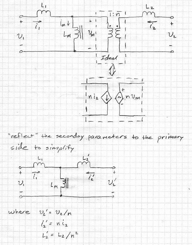
Then, applying KVL, we get this solution:
$$ \begin{align}
v_1 &=~ L_1 \dot {i_1} + L_m ( \dot...
Then, applying KVL, we get this solution:
$$ \begin{align}
v_1 &=~ L_1 \dot {i_1} + L_m ( \dot...

I don't really care much about your "first thought response" at this point. You aren't putting in the effort necessary to make progress here. These words don't mean anything to me. You need to study more. This is the only useful advice I can give at this point.Patch Cabbage said:My first thought response would be that the variable resistor is really big, but that leads to the ripple invert is biased to be slightly on all the time. Not for sure if it will ever go down to zero. It should but it might not. Also the ripple invert is fixed and the voltage output is variable so that's not so perfect either.
Admin
- 69,806
- 25,700
Patch Cabbage said:I'm not proficient in daw and I draw still with a pen and paper and not a mouse so sorry about all the sloppy schematics.
Baluncore said:Get a copy of LTspice, it is free from ADI.
@Patch Cabbage -- it's time for you to start working on your toolkit and skills for working with circuits if you want to keep going down this path. As @Baluncore says, LTSpice is a free download and it includes a schematic capture feature. Please download LTSpice for free and start to learn how to draw schematics using it. That is an important step on your journey to learning more about electronics and EE.

https://www.analog.com › resources › ltspice-simulator\
Science Advisor
Homework Helper
- 30,613
- 7,551
. . . . and you were careful not to do your diagram whilst riding on a bus or with a mouse. There is little excuse for not using a free drawing app (not a painting app), which makes lines straight and level.DaveE said:This is a quick schematic sketch I drew by hand about 40 years later.
A quick tiffle with contrast and brightness would render that photo as good as new.
Science Advisor
Gold Member
- 4,943
- 1,575
@Patch Cabbage do you realize that a correctly configured pass transistor(s) act to reduce ripple? Apparently not and apparently the experiments you have done have not proven this out. It is impossible to get anywhere farther than you have without understanding schematics. Arm waving and talking about pass transistors, rectifiers, and transformers and being able to point them out on a physical power supply is not the same as understanding how they work and why they are configured and connected the way they are.
Similar threads
- david90
- · Replies 10 ·
- Electrical Engineering
- Replies
- 10
- AndrewBourhis
- · Replies 3 ·
- Electrical Engineering
- Replies
- 3
- anameel
- · Replies 4 ·
- Mechanics
- Replies
- 4
- Pythagorean
- · Replies 7 ·
- Electrical Engineering
- Replies
- 7
Undergrad
Hydro-power output question(s)
- D-C
- · Replies 9 ·
- Mechanics
- Replies
- 9