BJT implementation of a flip flop circuit

6 replies · 8K views · last reply
kuchun
Messages
11
Reaction score
1
I want to know the BJT implementation of flip flop with the help of proper circuit diagram..
 
There are RS (set-reset) flip flops, D flip flops, JK flip flops, and maybe a few others that have no useful function or advantage over those already given.

Which one did you have in mind?

As BJT technology has waned over the past couple two or three decades, given over to MOS technology, you may have trouble finding an online BJT equivalent circuit for a flip flop of any sort.
 
If you go to Google and set it to IMAGES, you can get lots of flip flop circuits.

The common one used as a divide-by-2 is the bistable flip flop.
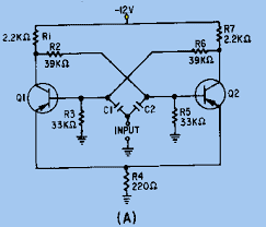
Schematic of a BJT bistable flip-flop circuit with two NPN transistors Q1 and Q2, cross-coupled through 39kΩ resistors R2 and R6, with 2.2kΩ collector resistors R1 and R7, 33kΩ base resistors R3 and R5, a 220Ω emitter resistor R4, a -12V supply, and an INPUT node at the center labeled (A).


As you can see, it uses a lot of components and also requires careful adjustment of the bias resistors. After that, it is quite reliable. I know of one that was made in 1972 and is still operating.

These days you would certainly use an integrated circuit.
 
Phrak said:
There are RS (set-reset) flip flops, D flip flops, JK flip flops, and maybe a few others that have no useful function or advantage over those already given.

Which one did you have in mind?

As BJT technology has waned over the past couple two or three decades, given over to MOS technology, you may have trouble finding an online BJT equivalent circuit for a flip flop of any sort.
I want to know the BJT implementation of RS flip flop...Thanks for ur reply
 
vk6kro said:
If you go to Google and set it to IMAGES, you can get lots of flip flop circuits.

The common one used as a divide-by-2 is the bistable flip flop.

Schematic of a BJT flip-flop circuit with two NPN transistors Q1 and Q2, resistors R1 to R7, a -12V supply, cross-coupled base and collector connections, and an INPUT node labelled C1 and C2.


As you can see, it uses a lot of components and also requires careful adjustment of the bias resistors. After that, it is quite reliable. I know of one that was made in 1972 and is still operating.

These days you would certainly use an integrated circuit.
Thanx for your reply...it was really helpful for me...Can u suggest me some good books on digital electronics, I am at beginner level..
 
You could read this description of R-S flip flops:
http://www.hobbyprojects.com/flip_flop/a_transistor_RS_flip_Flop.html

It describes this circuit:

Transistor R-S flip-flop schematic with two NPN transistors Tr1 and Tr2 cross-coupled through resistors R2 and R3, pull-up resistors R1 and R4 to +5 volts, outputs Q and Q-bar, and set and reset inputs; voltage labels at each node.


I have several books on digital techniques, but most of them are pretty old and possibly unavailable now. I wouldn't really recommend any of them.

This is a topic where you really need to get into a class and have someone cover it for you in a logical way.

That site above is part of a bigger tutorial on digital devices here:
http://www.hobbyprojects.com/flip_flop.html#flip-flop
It seems quite well done and you might like to start there.
 
vk6kro said:
The common one used as a divide-by-2 is the bistable flip flop.

Good grief. I've so long heard flip-flop and bistable flip-flop used synonymously that I don't recall every hearing the term "monostable flip-flop" used-- I had to look it up to see if it really was the same thing as a one shot.