Buck-boost converter output current limiter

10 replies · 7K views · last reply
Sid55
Messages
26
Reaction score
1
How can I get around current limiter of this buck-boost converter to achieve a lot higher current output than max rated current output for a very short amount of time ?

Does having high continuous current discharge power source at the input help it in any way ?

This buck-boost converter offers roughly the output power I need (80 - 120 Watts) but I need only low to moderate voltages (2.5V to 5.75V) to achieve those power levels.
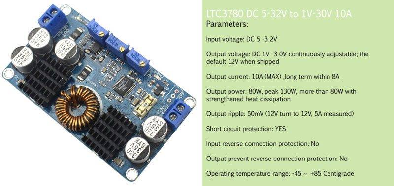
Blue LTC3780 DC-DC buck-boost converter board with two blue screw terminal blocks, three trim potentiometers, a toroidal inductor and black heatsinks, beside a spec sheet listing input 5-32V and output 1-30V 10A.


# Manufacturer max rating :-10 Amps, has 15 Amps onboard protection fuse

# Desired output current :- Up to 25 Amps for 5 seconds or less at a time

# For typical output voltage range : 2.5V to 5.75V

# Power input :- Parallel 2 X 3.6 V (nominal) + Parallel 2 X 3.6 V (nominal) in series (7.2V nominal) lithium-ion batteries with max continuous current discharge of 20 Amps per battery.

# Application :- Repurposing for DIY electronic cigarette (e-cig)

The product is listed here.
 
Attachments
  • Blue LTC3780 DC-DC buck-boost converter board with two blue screw terminal blocks, three trim potentiometers, a toroidal inductor and black heatsinks, beside a spec sheet listing input 5-32V and output 1-30V 10A.
    1.jpg
    44.8 KB · Views: 1,807
Last edited:
Sid55 said:
Does having high continuous current discharge power source at the input help it in any way ?
No.

Sid55 said:
Power input :- Parallel 2 X 3.6 V (nominal) + Parallel 2 X 3.6 V (nominal) in series (7.2V nominal) lithium-ion batteries with max continuous current discharge of 20 Amps per battery.
You should pick a different (just buck) converter rated for 25A. In theory this converter has an external current sense, so you might be able to modify the limit with replacing the resistor, but 2.5 times higher current is not OK with the inductor, the FETs, the PCB and the connectors. Also, since the dissipation will be at least 2.5 times higher the heatsinks will be definitely very busy.
 
berkeman said:
Do you have a local person who can mentor you on thie project?
No, unfortunately I don't.

berkeman said:
And from your previous thread, it looks like you are not real experienced in using electronics and batteries.
I'm not. That's why I'm here.

berkeman said:
And what does "repurposing an e-cig lighter" mean?
No idea what you mean by "e-cig lighter." I never mentioned "e-cig lighter" in my inquiry, if you bother to re-read my previous post.

Seems like you're confusing electronic lighter with electronic cigarette. Electronic lighter is purpose-designed/built to light up traditional cigarettes, the ones with tobacco wrapped with paper, whereas electronic cigarette is purpose-designed/built to heat up cotton soaked with thick liquid to vaporize the liquid. The vaporized liquid may or may not contain nicotine depending on user's customization.

Side-by-side comparison labelled Electronic lighter (left, a grey SPARX-branded lighter with a blue button and an arc-flash inset) and Electronic cigarette (right, a silver box-mod with a tank and a blue pen-style vaporiser).
My more fundamental question, aside from technical questions in my previous post, is how do buck-boost converters inside electronic cigarettes handle such insane levels of current discharge despite being built with no so beefy components while being incredibly tiny in physical size compared to buck-boost converter mentioned in my previous post ?
 
Attachments
  • Side-by-side comparison labelled Electronic lighter (left, a grey SPARX-branded lighter with a blue button and an arc-flash inset) and Electronic cigarette (right, a silver box-mod with a tank and a blue pen-style vaporiser).
    e-smoke.jpg
    39.9 KB · Views: 1,361
Sid55 said:
No idea what you mean by "e-cig lighter." I never mentioned "e-cig lighter" in my inquiry, if you bother to re-read my previous post.

Seems like you're confusing electronic lighter with electronic cigarette.
Oops, sorry for my brain fade. I don't use either, so I glossed over the details of what you asked. o0)
Sid55 said:
My more fundamental question, aside from technical questions in my previous post, is how do buck-boost converters inside electronic cigarettes handle such insane levels of current discharge despite being built with no so beefy components while being incredibly tiny in physical size compared to buck-boost converter mentioned in my previous post ?
That's a reasonable question. Do you have a schematic of such 25A e-cig circuits? As long as you take care with the safe operating area (SOA) of the semiconductors and size the important things correctly, you can take advantage of the low duty cycle of the 25A requirement.
 
Rive said:
You should pick a different (just buck) converter rated for 25A.

I have now come to agree with you.

The one I could find is SZBK07 300W 20A (listed here) buck converter though it does not seem to output high current discharge at low output voltages as demonstrated here -
 
berkeman said:
Do you have a schematic of such 25A e-cig circuits?

Texas Instruments has 200W 1V to 10V at 20A to 45A output synchronous 4-switch buck-boost converter design based on the LM5175 controller for e-cigarette applications. Schematic PDF here and test results PDF here. Overview here.Texas Instruments 200 Watts 1V to 10V at 20A to 45A output chipset board PMP20327
Green printed circuit board labelled LM5175 200W Buck Boost, with four power MOSFETs, a large inductor L1, shunt RS1 and output terminals J2 and J3, solution size 26mm x 60mm.

Evolv DNA 200 Watts 0.5V - 9V (up to 50A) output chipset board. Evolv DNA 200W datasheet here.
Green circuit board with a small OLED display showing 0.000, 0.00V, 450F and 200W, a micro USB port, two round push buttons and a ribbon cable connector.

Texas Instruments 200 Watts 1V to 10V at 20A to 45A schematic (screenshot from schematic PDF)

Schematic of a synchronous four-switch buck-boost converter built around an LM5175 controller, with input 6V to 8.6V and output 1V to 10V at 20A to 45A.
 
Attachments
  • Green printed circuit board labelled LM5175 200W Buck Boost, with four power MOSFETs, a large inductor L1, shunt RS1 and output terminals J2 and J3, solution size 26mm x 60mm.
    200W E-Cigarette Buck Boost.png
    91.4 KB · Views: 1,470
  • Green circuit board with a small OLED display showing 0.000, 0.00V, 450F and 200W, a micro USB port, two round push buttons and a ribbon cable connector.
    dna200.jpg
    25.4 KB · Views: 1,210
  • Schematic of a synchronous four-switch buck-boost converter built around an LM5175 controller, with input 6V to 8.6V and output 1V to 10V at 20A to 45A.
    Ca.JPG
    31.4 KB · Views: 1,706
Sid55 said:
whereas electronic cigarette is purpose-designed/built to heat up cotton soaked with thick liquid to vaporize the liquid.
So are there voltage and current standards in the industry for getting optimum vapors off of these modules? Are there datasheets available to the public, or are they mostly proprietary to the e-cig industry?
 
Sid55 said:
Texas Instruments has 200W 1V to 10V at 20A to 45A output synchronous 4-switch buck-boost converter design based on the LM5175 controller for e-cigarette applications. Schematic PDF here and test results PDF here. Overview PDF here.
Can you just use that?
 
berkeman said:
So are there voltage and current standards in the industry for getting optimum vapors off of these modules? Are there datasheets available to the public, or are they mostly proprietary to the e-cig industry?
E-cig chipset makers are limited by what they can get out of 3.6V (nominal) lithium-ion and lithium polymer batteries.

18650 3.6V (nominal) lithium-ion high continuous discharge battery is the most commonly available and the widely used power source. Used in single or dual (series) or triple (series) and quad (parallel-series) connection.

20700 3.6V (nominal) lithium-ion high continuous discharge battery is far less available than 18650 3.6V and is far less used power source.

21700 3.6V (nominal) lithium-ion high continuous discharge battery is just as far less available and is far less used power source as 20700 lithium-ion battery.

26650 3.6V (nominal) lithium-ion battery is almost exclusively used as a single battery power source e-cigs.

Lithium polymer batteries are most commonly used for powering low power (about 70 Watts or less) e-cigs and is rarely used in high power e-cigs due to lithium polymer battery's inherent volatility at very high current discharge and due to other risk factors.

Three red cylindrical lithium-ion cells standing side by side, from left to right: a large cell labelled IMR 26650, a medium cell labelled SANYO NCR20700B, and a small cell with no visible label.
 
Attachments
  • Three red cylindrical lithium-ion cells standing side by side, from left to right: a large cell labelled IMR 26650, a medium cell labelled SANYO NCR20700B, and a small cell with no visible label.
    JPH_Maxim.jpg
    20.5 KB · Views: 1,124
berkeman said:
Can you just use that?

I highly doubt the schematic would be drastically different from other e-cig chipset makers however components used more than likely would be.