Calculate Input Resistance: Formula & Tips
- Thread starter IronaSona
- Start date
-
- Tags
- Input Resistance
Click For Summary
SUMMARY
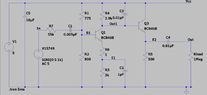
The discussion focuses on calculating input resistance using the formula R1(1+BA0) and emphasizes the importance of understanding the context, particularly regarding frequency. It highlights the need to simplify the network by ignoring negligible reactive components, such as considering 10KΩ + 1mΩ as just 10KΩ. The conversation also stresses the relevance of AC small signal models for analyzing input impedance, suggesting the use of a simplified transistor model to identify components that do not affect input current.
PREREQUISITES- Understanding of input resistance and impedance concepts
- Familiarity with AC small signal models in transistor circuits
- Knowledge of simplifying electrical networks
- Basic proficiency in circuit analysis techniques
- Research the application of AC small signal models in transistor analysis
- Learn about simplifying complex circuits for impedance calculations
- Explore the effects of frequency on input impedance
- Study practical examples of input resistance calculations in electronic circuits
Electrical engineers, circuit designers, and students studying electronics who need to calculate input resistance and understand impedance in AC circuits.
Similar threads
- · Replies 1 ·
- · Replies 12 ·
- · Replies 11 ·
- · Replies 6 ·
- · Replies 2 ·
- · Replies 14 ·
- · Replies 13 ·