Heexit
- 10
- 3
- Homework Statement
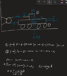
- On a trailer (mass M), there is a box (mass m). A rope runs from the box over a fixed pulley to the back end of the trailer. A pulling force F acts on the trailer. There is friction between the box and the trailer. The trailer is considered to be moving easily on the ground. Calculate the acceleration of the box relative to the ground (see picture for better understanding of question under Attempt at a Solution).
- Relevant Equations
- f = (mu)*FN, f=ma
Question picture:

My solution:

Where:
S is the lineforce
Ff is the force as a result of friction
a is the resulting acceleration
F is the acting force
The answear is supposed to be a=(F-2mg(mu))/(m+M)
Any idea what i could have missed?
Thanks for your help on beforehand!
My solution:
Where:
S is the lineforce
Ff is the force as a result of friction
a is the resulting acceleration
F is the acting force
The answear is supposed to be a=(F-2mg(mu))/(m+M)
Any idea what i could have missed?
Thanks for your help on beforehand!