Hashirama
- 2
- 0
- TL;DR
- In summary I am trying to lock the cavity using the modulation demodulation technique, but I need help with the signals I am getting.
Hello, So I am trying to lock an X cavity to a 1064 nm laser. Laser has a linewidth of ~100KHz, cavity linewidth is 37.65KHz, and the FSR is 3.125 MHz. When I try to scan the cavity, the peaks usually shift and after a few seconds, the resonance comes off. I am scanning the cavity at around 100 Hz, and I assume it has some high-frequency noise that contributes to the jitter.
To lock, I am using Lock In+PID method, but with very slow modulation (20-30 KHz), my piezo where I am sending the modulation (attached to one of the cavity mirrors) can go up to 340KHz.
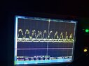
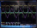
In the scanning image, the lock-in output is in green, the scanned peaks are in yellow. In PID image, blue one is error monitor and green is the output, I am not sure I am using it correctly.
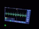
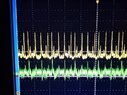
When I use the modulated signal, the lock-in output behaves strangely, like at the peaks, it gives some signal, but whether it is the derivative or not cant be said. Same when it goes to PID.
I am attaching some pictures of what I got. Can someone please help me identify if it is right?
Thanks a lot!
To lock, I am using Lock In+PID method, but with very slow modulation (20-30 KHz), my piezo where I am sending the modulation (attached to one of the cavity mirrors) can go up to 340KHz.
In the scanning image, the lock-in output is in green, the scanned peaks are in yellow. In PID image, blue one is error monitor and green is the output, I am not sure I am using it correctly.
When I use the modulated signal, the lock-in output behaves strangely, like at the peaks, it gives some signal, but whether it is the derivative or not cant be said. Same when it goes to PID.
I am attaching some pictures of what I got. Can someone please help me identify if it is right?
Thanks a lot!