Deriving Formula for Magnetic Torque on Semicircular Loop

Click For Summary

Discussion Overview

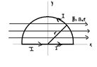
The discussion revolves around deriving a formula for the magnetic torque on a semicircular loop in a magnetic field. Participants explore the calculations of magnetic forces and torques, addressing both theoretical and mathematical aspects of the problem.

Discussion Character

  • Technical explanation
  • Mathematical reasoning
  • Debate/contested

Main Points Raised

  • One participant presents initial calculations for the magnetic force on both the non-curved and curved sections of the loop, expressing uncertainty about the correctness of their approach.
  • Another participant clarifies that torque should be calculated with respect to an axis and provides a general formula for torque, emphasizing the need to consider the Lorentz force on different parts of the loop.
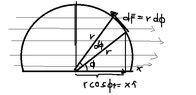
  • It is noted that the total force on the loop is zero, which leads to a discussion about the necessity of using integration to account for varying forces along the loop.
  • Questions are raised regarding the integration process, specifically about the derivation of certain terms and the limits of integration.
  • Participants discuss the relationship between the Lorentz force, the geometry of the loop, and the calculation of torque, highlighting the complexity of the problem.

Areas of Agreement / Disagreement

Participants generally agree on the need for integration in calculating torque due to the varying forces along the loop. However, there remains uncertainty and confusion about specific steps in the derivation and the application of the formulas.

Contextual Notes

Some participants express confusion regarding the integration limits and the derivation of certain expressions, indicating that there are unresolved mathematical steps and assumptions that need clarification.

Who May Find This Useful

This discussion may be useful for students and practitioners interested in electromagnetism, particularly those looking to understand the derivation of torque in magnetic systems involving loops and the application of the Lorentz force.

Drain Brain
Messages
143
Reaction score
0

I'm trying to derive a formula for the magnetic torque on a semicircular loop.

what I've done so far is this

The magnetic force on the non-curved loop is
$\vec{F}_{x}=\int Idx\hat{i}\times B_{\circ}\hat{i}=0N$

for the curved loop

$\vec{F}_{c}=\int_{0}^{\pi} Ird\phi\hat{\phi}\times B_{\circ}\hat{r}=-2B_{\circ}Ir\hat{k}$I'm not sure if what I've done is correct. This is all I can do. Can you please help me finish it. Thanks!
 

Attachments

  • emagse.jpg
    emagse.jpg
    11.7 KB · Views: 113
Last edited:
Mathematics news on Phys.org
Drain Brain said:
I'm trying to derive a formula for the magnetic torque on a semicircular loop.

what I've done so far is this

The magnetic force on the non-curved loop is
$\vec{F}_{x}=\int Idx\hat{i}\times B_{\circ}\hat{i}=0N$

for the curved loop

$\vec{F}_{c}=\int_{0}^{\pi} Ird\phi\hat{\phi}\times B_{\circ}\hat{r}=-2B_{\circ}Ir\hat{k}$I'm not sure if what I've done is correct. This is all I can do. Can you please help me finish it. Thanks!

Hi Drain Brain! (Smile)

A torque is calculated with respect to an axis.
The general formula is:
$$\boldsymbol\tau = \mathbf r \times \mathbf F$$
where $\mathbf r$ is a vector from the axis to the point where the force is applied.

However, what you have calculated is the total force instead of the torque.

Note that the lorentz force on the right half is into the paper, while the lorentz force on the left half is coming out of the paper.
The logical axis is therefore the y-axis.
(Btw, it also means that the total force on the curve is zero instead of what you have - there's a calculation mistake in there.)

To get the torque with respect to the y-axis, we'd need:
$$\boldsymbol\tau = \int x\boldsymbol{\hat \imath} \times d\mathbf{F}
= \int x\boldsymbol{\hat \imath} \times (I\, d\boldsymbol{\ell} \times \mathbf{B})
= \int r\cos\phi\,\boldsymbol{\hat \imath} \times (I\, rd\phi\, \boldsymbol{\hat\phi} \times B_\circ\boldsymbol{\hat\imath})
$$
$$\boldsymbol\tau = \int r\cos\phi\,\boldsymbol{\hat \imath} \times (B_\circ I r\, d\phi \cdot -\cos\phi\, \mathbf{\hat k})
= B_\circ I r^2\int -\cos^2 \phi\, d\phi \cdot -\boldsymbol{\hat \jmath}
= B_\circ I r^2 \boldsymbol{\hat \jmath}\int \cos^2 \phi\, d\phi
$$
(Wasntme)
 
I like Serena said:
Hi Drain Brain! (Smile)

A torque is calculated with respect to an axis.
The general formula is:
$$\boldsymbol\tau = \mathbf r \times \mathbf F$$
where $\mathbf r$ is a vector from the axis to the point where the force is applied.

However, what you have calculated is the total force instead of the torque.

Note that the lorentz force on the right half is into the paper, while the lorentz force on the left half is coming out of the paper.
The logical axis is therefore the y-axis.
(Btw, it also means that the total force on the curve is zero instead of what you have - there's a calculation mistake in there.)

To get the torque with respect to the y-axis, we'd need:
$$\boldsymbol\tau = \int x\boldsymbol{\hat \imath} \times d\mathbf{F}
= \int x\boldsymbol{\hat \imath} \times (I\, d\boldsymbol{\ell} \times \mathbf{B})
= \int r\cos\phi\,\boldsymbol{\hat \imath} \times (I\, rd\phi\, \boldsymbol{\hat\phi} \times B_\circ\boldsymbol{\hat\imath})
$$
$$\boldsymbol\tau = \int r\cos\phi\,\boldsymbol{\hat \imath} \times (B_\circ I r\, d\phi \cdot -\cos\phi\, \mathbf{\hat k})
= B_\circ I r^2\int -\cos^2 \phi\, d\phi \cdot -\boldsymbol{\hat \jmath}
= B_\circ I r^2 \boldsymbol{\hat \jmath}\int \cos^2 \phi\, d\phi
$$
(Wasntme)
HI I LIKE SERENA!
why did you use integration in getting the torque? I thought it would be just a plug-and-chug method after I determine the forces on each piece of the loop. I'm still confused.
 
Drain Brain said:
HI I LIKE SERENA!
why did you use integration in getting the torque? I thought it would be just a plug-and-chug method after I determine the forces on each piece of the loop. I'm still confused.

We need an integral because the Lorentz force on each part of the loop is different and each part also has a different distance to the axis of rotation.
Leaving out the integral is only possible if we're talking about specific forces that act at specific distances - not if they change gradually.
For example if we had a rectangular loop.

We could get rid of all the unit vectors that make the formulas less readable.
 
I'm going to present this problem tomorrow. That's why I badly need to understand how to do it

this is the what I did first when I tried to solve it

first I took the lorentz forces on each piece of the loop

for the non-curved part I get $0N$

for the curved part(right) I get $-IB_{\circ}r\boldsymbol{\hat{z}}$

for the curved part(left) I get $IB_{\circ}r\boldsymbol{\hat{z}}$

which when we add will become 0 net force.

now that I determined the lorentz forces

I have to solve for

the torque where I have to plug those in. But now since it's not as simple as I expected it to be, I really want to understand the method that you posted here.

first there are things I want to know about your solution

where did you get $x\boldsymbol{\hat \imath}$? and why did you cross it to $dF$(which I suppose the lorentz force of the first curved(right))

and also how did you arrive from $x\boldsymbol{\hat \imath}$ to $r\cos\phi\,\boldsymbol{\hat \imath}$

and from $(I\, d\boldsymbol{\ell} \times \mathbf{B})$ to $(B_\circ I r\, d\phi \cdot -\cos\phi\, \mathbf{\hat k})$

and lastly what's the limit of integreation?

I know it's a lot of queries. Please bear with me as I want to really understand it fully. Thanks!
 
Drain Brain said:
for the non-curved part I get $0N$

for the curved part(right) I get $-IB_{\circ}r\boldsymbol{\hat{z}}$

for the curved part(left) I get $IB_{\circ}r\boldsymbol{\hat{z}}$

which when we add will become 0 net force.

All correct. (Smile)
now that I determined the lorentz forces

I have to solve for

the torque where I have to plug those in. But now since it's not as simple as I expected it to be, I really want to understand the method that you posted here.

first there are things I want to know about your solution

where did you get $x\boldsymbol{\hat \imath}$? and why did you cross it to $dF$(which I suppose the lorentz force of the first curved(right))

and also how did you arrive from $x\boldsymbol{\hat \imath}$ to $r\cos\phi\,\boldsymbol{\hat \imath}$

Torque is perpendicular displacement times force.

You have found a total lorentz force on the right part of the loop.
But what is its displacement with respect to the axis?
There is no one such displacement - it varies along the loop.

Suppose we pick one small section of the loop.
Say between angles $\phi$ and $\phi + d\phi$, where $d\phi$ is a sufficiently small angle so we can assume that the lorentz force on the section is more or less constant.

Then we can determine the displacement to the axis and we can find the lorentz force on this section.

The perpendicular displacement from the y-axis is the x-coordinate.
In polar coordinates that is $x=r\cos\phi$.
The corresponding vector, that already happens to be perpendicular to the force, is $x\boldsymbol{\hat \imath}$.

The lorentz force is current times length times magnetic field strength, or $\mathbf F_{lorentz} = I(\boldsymbol{\ell} \times \mathbf B)$.
Since we're talking about a small section with length $d\boldsymbol \ell$, we have a corresponding small contribution to the lorentz force $d\mathbf F_{lorentz}$.

and from $(I\, d\boldsymbol{\ell} \times \mathbf{B})$ to $(B_\circ I r\, d\phi \cdot -\cos\phi\, \mathbf{\hat k})$

$d\boldsymbol{\ell}$ is the vector representing our small section of the loop.
It has length $rd\phi$ and direction $\boldsymbol{\hat\phi}$.
From your drawing, the magnetic field strength is given by $\mathbf{B} = B_\circ \boldsymbol{\hat \imath}$.

Before I write a couple of pages of text that won't help you anyway, can you clarify how much you understand and where you are missing something? (Wondering)
and lastly what's the limit of integration?

I had left out the limits so as not to distract from what is really going on.
On the straight section, the lorentz force is zero everywhere, so this does not contribute to the torque.
That leaves the circular section running from $\phi=0$ to $\pi$.
 
Now it's clear to me where those pieces came from!

What confused me is when you use integration in finding the torque, but that is also clear to me now.

Moving on, is $d\mathbf F_{lorentz}$ only for the right part of the curve or for the entire curve?

and also did you just change the cross product to dot product in this from $(I\, rd\phi\, \boldsymbol{\hat\phi} \times B_\circ\boldsymbol{\hat\imath})$ to $(B_\circ I r\, d\phi \cdot -\cos\phi\, \mathbf{\hat k})$?

I think I'm getting close to understanding it.
 
Drain Brain said:
Now it's clear to me where those pieces came from!

What confused me is when you use integration in finding the torque, but that is also clear to me now.

Moving on, is $d\mathbf F_{lorentz}$ only for the right part of the curve or for the entire curve?

It's for the entire curve.
Only when $\phi$ is first introduced in the formula does it become specific for the curved section.
and also did you just change the cross product to dot product in this from $(I\, rd\phi\, \boldsymbol{\hat\phi} \times B_\circ\boldsymbol{\hat\imath})$ to $(B_\circ I r\, d\phi \cdot -\cos\phi\, \mathbf{\hat k})$?

I think I'm getting close to understanding it.

The tangent unit vector is:
$$\boldsymbol{\hat\phi}=\begin{pmatrix}-\sin\phi \\ \cos\phi \\ 0\end{pmatrix}$$
The unit vector in the direction of the magnetic field strength is:
$$\boldsymbol{\hat\imath}=\begin{pmatrix}1 \\ 0 \\ 0\end{pmatrix}$$

Therefore their cross product is:
$$\boldsymbol{\hat\phi} \times \boldsymbol{\hat\imath}
=\begin{pmatrix}-\sin\phi \\ \cos\phi \\ 0\end{pmatrix} \times \begin{pmatrix}1 \\ 0 \\ 0\end{pmatrix}
=\begin{pmatrix}0 \\ 0 \\ -\sin\phi \cdot 0 - \cos\phi\cdot 1\end{pmatrix}
=\begin{pmatrix}0 \\ 0 \\ - \cos\phi\end{pmatrix}
=-\cos\phi \,\mathbf{\hat k}
$$

Thus:
$$(I\, rd\phi\, \boldsymbol{\hat\phi} \times B_\circ\boldsymbol{\hat\imath})
= I\, rd\phi\,B_\circ (\boldsymbol{\hat\phi}\times \boldsymbol{\hat\imath})
= I\, rd\phi\,B_\circ (-\cos\phi \,\mathbf{\hat k})
= I\, rd\phi\,B_\circ \cdot -\cos\phi \,\mathbf{\hat k}
$$

It's not a dot product, it's regular multiplication. (Wasntme)
 

finishing up with the problem,$\boldsymbol\tau=B_\circ I r^2 \boldsymbol{\hat \jmath}\int \cos^2 \phi\, d\phi$

$\boldsymbol\tau=B_\circ I r^2 \boldsymbol{\hat \jmath}\int_{0}^{\pi} \frac{1+\cos(2\phi)}{2}d\phi$

$\boldsymbol\tau=B_\circ I r^2 \boldsymbol{\hat \jmath}\int_{0}^{\pi} \frac{1+\cos(2\phi)}{2}d\phi = B_\circ I r^2 \boldsymbol{\hat \jmath}[\frac{1}{2}+\frac{\sin(2\phi)}{4}]_{0}^{\pi}$

$\boldsymbol\tau=\frac{B_\circ I r^2 \boldsymbol{\hat \jmath}\pi }{2}$ --->>>> My final answer is this correct?
 
  • #10
Drain Brain said:
--->>>> My final answer is this correct?

Yup. (Mmm)
 
  • #11
I redraw the image that I posted above can you check if they are correct.
 

Attachments

  • emagsse.jpg
    emagsse.jpg
    17.5 KB · Views: 95
  • #12
Drain Brain said:
I redraw the image that I posted above can you check if they are correct.

Well...
  • It's not running from 0 to $\pi$ anymore - it's doing a bit more now.
  • What you have drawn as $d\mathbf F$ should instead be $d\boldsymbol \ell = r d\phi\, \boldsymbol{\hat\phi}$ and it should be slightly shorter, connecting the 2 radial line segments.
  • There should be an additional vector $d\mathbf F$ going into the paper.
(Wasntme)
 

Similar threads

Replies
4
Views
2K
Replies
3
Views
2K
Replies
12
Views
2K
  • · Replies 25 ·
Replies
25
Views
2K
Replies
1
Views
1K
Replies
1
Views
2K
Replies
17
Views
3K
Replies
4
Views
2K
  • · Replies 17 ·
Replies
17
Views
14K
  • · Replies 4 ·
Replies
4
Views
3K