JC2000
- 186
- 16
- TL;DR
- I am trying to design a buck converter that meets the following criteria :
Maximum output voltage = 12 V
Output Current = 15 A
Maximum input voltage = 24 V
I had a bunch of questions regarding the feedback component as well as the feedback mechanism itself.

1. I am using the attached schematic as reference for my design. As per the LM2576 module data sheet, it can handle a maximum current of 3 A whereas I need the IC to handle at least 15 A. After digging around a little this was one buck converter that seems to be able to handle 15 A. However, the video says that this buck converter uses the IRFB3607 MOSFET. Does this mean that unlike the schematic above, in the case of the module in the video, the MOSFET that acts as a switch is a separate component from the controller IC? If so, what is the IC being used, what search parameters should I use to find such ICs?
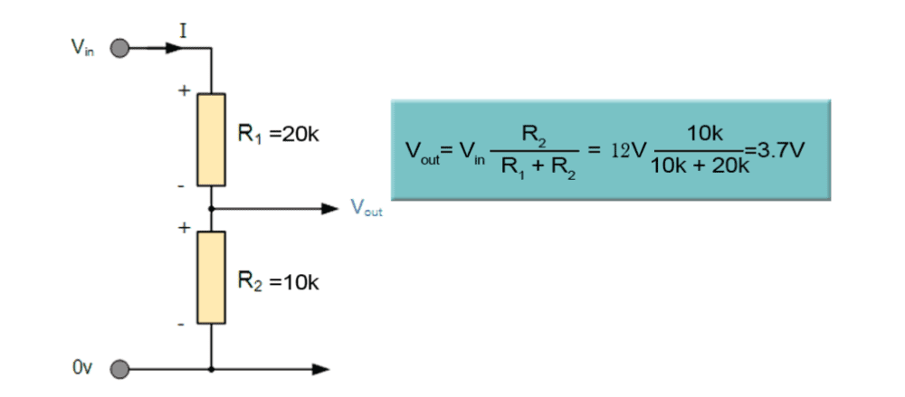
2. Coming to the regulated output voltage, my understanding is as follows... since I decide ##V_{in}##, if I want a specific ##V_{out}##, the equation above would give me the required ratio of resistances. Essentially, I need to have a potentiometer which must be manually adjusted to get the desired output voltage. If my understanding correct so far, why is the feedback wire NOT connected to the ##V_{out}## node in the first schematic? Or is it that there is a mistake in the first schematic and the point between ##R_1## and ## R_2## is the actual ##V_{out}##? In fact, I am unable to pin down the exact role of the feedback pin. Under what circumstances would the output voltage fluctuate (would it fluctuate if the load were to suddenly draw more current or if its resistance changed for some reason)?
3. In the buck converter module from the video, there is a current control potentiometer as well. Is this essentially a variable resistor in series with ##V_{out}##?
1. I am using the attached schematic as reference for my design. As per the LM2576 module data sheet, it can handle a maximum current of 3 A whereas I need the IC to handle at least 15 A. After digging around a little this was one buck converter that seems to be able to handle 15 A. However, the video says that this buck converter uses the IRFB3607 MOSFET. Does this mean that unlike the schematic above, in the case of the module in the video, the MOSFET that acts as a switch is a separate component from the controller IC? If so, what is the IC being used, what search parameters should I use to find such ICs?
2. Coming to the regulated output voltage, my understanding is as follows... since I decide ##V_{in}##, if I want a specific ##V_{out}##, the equation above would give me the required ratio of resistances. Essentially, I need to have a potentiometer which must be manually adjusted to get the desired output voltage. If my understanding correct so far, why is the feedback wire NOT connected to the ##V_{out}## node in the first schematic? Or is it that there is a mistake in the first schematic and the point between ##R_1## and ## R_2## is the actual ##V_{out}##? In fact, I am unable to pin down the exact role of the feedback pin. Under what circumstances would the output voltage fluctuate (would it fluctuate if the load were to suddenly draw more current or if its resistance changed for some reason)?
3. In the buck converter module from the video, there is a current control potentiometer as well. Is this essentially a variable resistor in series with ##V_{out}##?
