QuantumLollipop
- 7
- 0
Hey all,
I'm stuck on this problem and not sure how to proceed/if I'm in the right direction.
Problem: One reference frame N sits at the origin (inertial frame) while another frame, B, describes a disk rolling on a circular ring about the other frame. Picture below
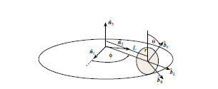 (A) find the direction cosine matrix [BN] in terms of angle phi
(B) Given a vector in the B frame find the vector in the N frame
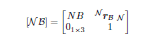
Relevant Equations: The direction cosine matrix of a homogeneous system such as this is a 4x4 matrix whose elements are: top left ([BN], rotation matrix as if centered at origin)3x3, top right (a vector from the origin of N frame to origin of B frame)3x1, bottom left (0)1x3, bottom right (1)1x1 = [NB]4x4
 Attempt:
The position vector was relatively easy to compute:
r(N)=L*cos(Φ) n1^ + L*sin(Φ) n2^ + r n3^ (I hope that's right)
Next, to complete the full matrix I need to find the direction cosine matrix NB which I believe is computed as if B were sitting at the origin.
I'm having difficulty with this part, I assume the only way to find this is using the 3 consecutive Euler Angles. My trouble is finding which Euler Angles to use for the rotation. Any help would be appreciated. Apologies for the crude equations, I was having troubles with the equation editor and couldn't figure out how to make matrices. Thanks
I'm stuck on this problem and not sure how to proceed/if I'm in the right direction.
Problem: One reference frame N sits at the origin (inertial frame) while another frame, B, describes a disk rolling on a circular ring about the other frame. Picture below
(B) Given a vector in the B frame find the vector in the N frame
Relevant Equations: The direction cosine matrix of a homogeneous system such as this is a 4x4 matrix whose elements are: top left ([BN], rotation matrix as if centered at origin)3x3, top right (a vector from the origin of N frame to origin of B frame)3x1, bottom left (0)1x3, bottom right (1)1x1 = [NB]4x4
The position vector was relatively easy to compute:
r(N)=L*cos(Φ) n1^ + L*sin(Φ) n2^ + r n3^ (I hope that's right)
Next, to complete the full matrix I need to find the direction cosine matrix NB which I believe is computed as if B were sitting at the origin.
I'm having difficulty with this part, I assume the only way to find this is using the 3 consecutive Euler Angles. My trouble is finding which Euler Angles to use for the rotation. Any help would be appreciated. Apologies for the crude equations, I was having troubles with the equation editor and couldn't figure out how to make matrices. Thanks
Last edited:
