Draw out the circuit diagram for the following 2 output circuit

Click For Summary

Discussion Overview

The discussion revolves around interpreting a Verilog module for a digital circuit and drawing its corresponding circuit diagram. Participants explore the syntax and semantics of the Verilog code, particularly focusing on the output assignments and the correct usage of operators.

Discussion Character

  • Technical explanation
  • Debate/contested
  • Mathematical reasoning

Main Points Raised

  • One participant questions the expression "f(~y&~x)" as it appears to suggest a function application without proper declaration, leading to confusion about its validity in the context of Verilog.
  • Another participant clarifies that "f" in "f(~y&~x)" should be interpreted as a variable rather than a function, indicating that the expression is meant to represent a logical operation rather than a function call.
  • Several participants discuss the importance of syntax in Verilog, noting that "module" should be lowercase and that the semicolon after "endmodule" is incorrect.
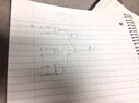
  • A participant mentions successfully compiling the corrected code and expresses uncertainty about how to draw the circuit diagram based on the logic described in the code.
  • Another participant outlines the steps for drawing the circuit, detailing how inputs are processed through AND and OR gates based on the logic defined in the module.

Areas of Agreement / Disagreement

Participants express differing interpretations of the Verilog code, particularly regarding the role of "f" and the syntax used. While some agree on the need for careful attention to syntax, there is no consensus on the initial interpretation of the code.

Contextual Notes

Limitations include unresolved questions about the correct interpretation of the Verilog syntax and the implications of the logical operations defined in the module. Participants have not reached a definitive conclusion on the circuit representation.

Who May Find This Useful

This discussion may be useful for individuals interested in digital circuit design, Verilog programming, or those seeking clarification on syntax and logical operations in hardware description languages.

shamieh
Messages
538
Reaction score
0
Draw out the circuit diagram for the following 2 output circuit specified in the following Verilog module (AND - &, Or - |, Not - ~). Use AND, OR and Inverter Gates.

Module test1(f,g,x,y,z);
input x,y,z;
output f,g;

assign g = f(~y&~x);
assign f = x&y | ~x&z;
endmodule;

Here is my solution:

View attachment 1449
 

Attachments

  • photo(2).JPG
    photo(2).JPG
    25.6 KB · Views: 109
Technology news on Phys.org
shamieh said:
Module test1(f,g,x,y,z);
input x,y,z;
output f,g;

assign g = f(~y&~x);
assign f = x&y | ~x&z;
endmodule;
I am not familiar with Verilog (I am using another software that uses file extension .v :)), but I don't understand "f(~y&~x)". Since there is no operator between f and (~y&~x), it looks like a function application, but f has not been declared a function (this requires the "function" keyword). I tried to compile this code on www.compileonline.com, and it seems to say the same thing:
Code:
main.v:5: error: No function f in this context (test1).
main.v:5: error: Unable to elaborate r-value: f((~(y))&(~(x)))

Besides, "module" in Verilog is written with a lowercase m and apparently there should not be a semicolon after "endmodule". If you want to design circuits, you have to be extra careful about such things.
 
the f in f(~y&~x) means like the function f. So it's essentially saying that the function g = f (f = x&y | ~x&z;) OR (~y&~x); see what I'm saying?

and the endmodule should have been lower case. Mistake on my part.
 
Evgeny.Makarov said:
I am not familiar with Verilog (I am using another software that uses file extension .v :)), but I don't understand "f(~y&~x)". Since there is no operator between f and (~y&~x), it looks like a function application, but f has not been declared a function (this requires the "function" keyword). I tried to compile this code on www.compileonline.com, and it seems to say the same thing:
Code:
main.v:5: error: No function f in this context (test1).
main.v:5: error: Unable to elaborate r-value: f((~(y))&(~(x)))

Besides, "module" in Verilog is written with a lowercase m and apparently there should not be a semicolon after "endmodule". If you want to design circuits, you have to be extra careful about such things.

I got mine to compile fine. It was a typo on my part originally i put a semicolon at the end which was wrong, but if you copy and paste this in the compiler you just linked me, it compiles and executes fine. But how do I actually draw this monster?:eek: Here is the code that will compile below if you want to try for yourself.
Code:
module test1(f,g,x,y,z);
    input x,y,z;
    output f,g;
    
    assign g = f|(~y&~x);
    assign f = x&y|~x&z;
endmodule
 
shamieh said:
Code:
module test1(f,g,x,y,z);
    input x,y,z;
    output f,g;
    
    assign g = f|(~y&~x);
    assign f = x&y|~x&z;
endmodule
This makes a big difference because now there is an OR after f. So f is not a function, but a regular variable. Before, even if f had been declared a function using the "function" keyword, it would have been unclear how f, which depends on two inputs x and y, can be applied to a single argument (~y&~x).

If you understand the order of evaluation, drawing a circuit is easy.

(1) x and y go to an AND
(2) x gets inverted and with z goes to an AND
(3) outputs of (1) and (2) go to an OR
(4) y and x get inverted and to to an AND
(5) outputs of (3) and (4) go to an OR.
 

Similar threads

Replies
1
Views
3K
  • · Replies 4 ·
Replies
4
Views
3K
  • · Replies 1 ·
Replies
1
Views
3K
Replies
6
Views
2K
  • · Replies 9 ·
Replies
9
Views
2K
  • · Replies 59 ·
2
Replies
59
Views
11K
  • · Replies 31 ·
2
Replies
31
Views
4K
  • · Replies 8 ·
Replies
8
Views
4K
  • · Replies 8 ·
Replies
8
Views
2K
  • · Replies 23 ·
Replies
23
Views
3K