Bluskyz
- 20
- 0
Just a quick apology for the long post. Recently I have been looking into digital circuit design and how karnaugh maps can help you simplify a logic table to simple gates. I extended this idea to trying to derive the most efficient full adder design and came up with the following logic table for two 1-bit inputs (a and b) for the current bits being added and a carry in(c):
x-y-c-a1-a0
0-0-0-0-0
0-0-1-0-1
0-1-0-0-1
0-1-1-1-0
1-0-0-0-1
1-0-1-1-0
1-1-0-1-0
1-1-1-1-1
Then I made the karnaugh maps corresponding to the outputs, one for the most significant bit and another for the other bit.
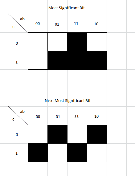
At this point I began looking at the map for the most significant bit and noted the groupings and turning them into a logical equation.
ab+ac+bc
With this, I don't really think that you can simplify this problem very much. I just simplified out the carry bit resulting in:
ab+c(a+b)
The story is similar with the next significant bit but due to the fact that there aren't any groupings in the karnaugh map, it really can't be simplified. I ended up with the following:
_
c(a[itex]\odot[/itex]b)+c(a[itex]\oplus[/itex]b)
After taking these final equations for the two outputs bits, I combined them into the final circuit. This should be a simplified form of a full adder.
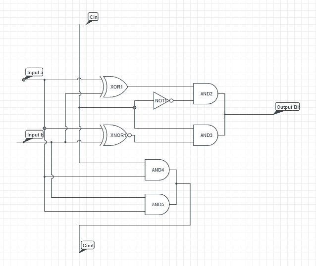
Comparing this to a fully simplified version of a full adder here:
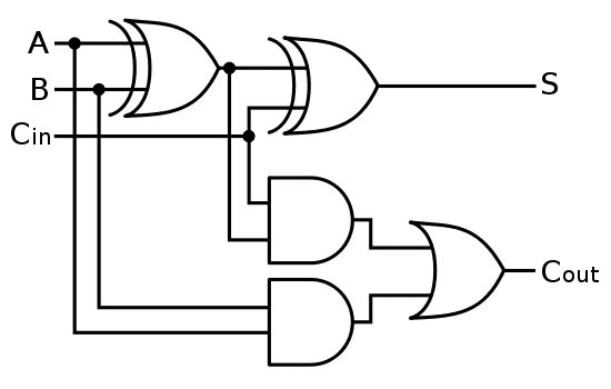
Both circuits are very similar its just mine seems to have a few more unessesary gates. Firstly, it seems that my xnor gate can simply be an xor wired to the output of the first xor gate and the carry in. Secondly, the additional and gates after the xor and xnor gates on my circuit can be completely omitted. My ultimate question is this: Is there a methodical way in which I can find the most simplified circuit for a corresponding truth table without resorting to brute force and examination of which parts can be omitted, changed, etc? Thank you for your help.
x-y-c-a1-a0
0-0-0-0-0
0-0-1-0-1
0-1-0-0-1
0-1-1-1-0
1-0-0-0-1
1-0-1-1-0
1-1-0-1-0
1-1-1-1-1
Then I made the karnaugh maps corresponding to the outputs, one for the most significant bit and another for the other bit.
At this point I began looking at the map for the most significant bit and noted the groupings and turning them into a logical equation.
ab+ac+bc
With this, I don't really think that you can simplify this problem very much. I just simplified out the carry bit resulting in:
ab+c(a+b)
The story is similar with the next significant bit but due to the fact that there aren't any groupings in the karnaugh map, it really can't be simplified. I ended up with the following:
_
c(a[itex]\odot[/itex]b)+c(a[itex]\oplus[/itex]b)
After taking these final equations for the two outputs bits, I combined them into the final circuit. This should be a simplified form of a full adder.
Comparing this to a fully simplified version of a full adder here:
Both circuits are very similar its just mine seems to have a few more unessesary gates. Firstly, it seems that my xnor gate can simply be an xor wired to the output of the first xor gate and the carry in. Secondly, the additional and gates after the xor and xnor gates on my circuit can be completely omitted. My ultimate question is this: Is there a methodical way in which I can find the most simplified circuit for a corresponding truth table without resorting to brute force and examination of which parts can be omitted, changed, etc? Thank you for your help.
Attachments
