Electric Flux - confused about integrating over a tilted area

Click For Summary
SUMMARY

This discussion centers on the calculation of electric flux through a tilted surface in the presence of an electric field. The formula for electric flux, given by the equation Φ = E·Acos(α), is clarified, emphasizing that only the component of the electric field in the direction of the area vector contributes to the flux. The contributors confirm that the Ex component does not contribute to the flux through the surface, as it is perpendicular to the area vector. The discussion concludes with a detailed parametrization of the surface for accurate flux calculation.

PREREQUISITES
  • Understanding of electric flux and its mathematical representation.
  • Familiarity with vector components in the context of electric fields.
  • Knowledge of surface parametrization techniques in vector calculus.
  • Basic grasp of trigonometric functions, particularly cosine.
NEXT STEPS
  • Study the derivation of electric flux using the formula Φ = E·Acos(α).
  • Learn about surface parametrization in vector calculus for complex geometries.
  • Explore the implications of electric field direction on flux calculations.
  • Investigate applications of electric flux in electromagnetic theory.
USEFUL FOR

Physics students, electrical engineers, and anyone interested in understanding electric fields and their interaction with surfaces will benefit from this discussion.

gionole
Messages
281
Reaction score
24
I have been thinking today about electric flux and it got me (as always) into confusion. I love to dig deeper and sometimes, I deviate from the truth.

Let's consider the tilted surface where Electric field is passing by. I'm attaching the image as well. I know that to calculate flux, we must do `EAcosa` (for simplicity, E is uniform, so no integral needed)

As we know, any vector(V) in x-y plane has two components. (Vx, Vy). On x-y plane, it seems easy to even see this in drawing.

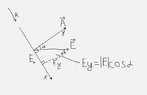
Since electric field is also a vector, it will have Ex, Ey as far as I can see(let's forget Ez for now). On the image(I drew it), you can see `Ex` and `Ey` components of E vector. They are x and y components of E because our x-y plane is a little bit different(to see it better, you have to rotate your head :rolleyes:)

Now, the funny thing is in the calculation of flux, Ex is not included, only Ey and we get AEcosa(true that `a` is angle between E and A, but from my image, we use the 2nd angle which is the same). I'm wondering why Ex is not included. Here is my reasoning. Well I understand that Ex component goes into the `x` direction, but it still has magnitude(non-zero) and why are we saying that it's not contributing to the flux ? For sure, it's not contributing to the Ey direction, but we not only have Ey, but Ex too. It seems to me that we're only curious about the electric field strength pointed to y direction only.

If you say that we want to maximize flux, I won't agree with you since we're not maximizing anything, but rather our flux will be less by using cosa. I've searched the internet, but couldn't find what I was looking for. Maybe simple discussion would do it for me.

Maybe, I'm wrong but maybe if you look at the picture again, we can imagine that Ex has the same direction as if we would imagine electric field lines pointed in the `k` direction and if we imagine `k` field line, it just hits the surface from outward and none of it(even one bit of it) "pass" through the surface, hence we don't include it.

Is everything I said correct ?
 

Attachments

  • Screenshot 2023-06-08 at 11.59.46 PM.png
    Screenshot 2023-06-08 at 11.59.46 PM.png
    10.4 KB · Views: 137
Last edited:
Physics news on Phys.org
To find the flux one looks at the speed times the perpendicular area or the area times the perpendicular speed. They give the same result.
 
hutchphd said:
To find the flux one looks at the speed times the perpendicular area or the area times the perpendicular speed. They give the same result.
I have a hard time imagining the speed notion. I think the best way you can help me is to agree with the whole thing I said or tell me where the flaw is. Refresh the page though, I editted. Thanks so much in advance.
 
gionole said:
It seems to me that we're only curious about the electric field strength pointed to y direction only
Your area vector is in the ##y## direction (if I understand your drawing correctly). So the component of the electric field in the ##x## does not provide any flux. Only the component of the electric field in the ##y## direction. It isn't a lack of curiosity about the ##x## direction, just that component provides no flux through the area.
 
Dale said:
Your area vector is in the ##y## direction (if I understand your drawing correctly). So the component of the electric field in the ##x## does not provide any flux. Only the component of the electric field in the ##y## direction.

@Dale

Yes, you're right. I have questions to confirm my understanding Dale, so all you have to do is tell me which statement below is incorrect.

1. Are my Ex and Ey components drawn correctly ?
2. Am I right that x-y plane for us to see better, we need to rotate our head to right. I'm asking this strange question because in school, we're all used to seeing x-y plane as we look at the image, but here, it's rotated. I'm asking this because I did the whole image, components by myself and wondering if the idea of what I'm saying is correct.
2. we can imagine that Ex has the same direction as if we would imagine electric field lines pointed in the `k` direction(see image) and if we imagine `k` field line, it just hits the surface and doesn't "pass" through it(even one bit of it) , hence we don't include Ex due to this reason.
 
You have ##~~d\Phi_E=\mathbf{E}\cdot\mathbf{\hat n}~dA##.

According to your coordinate system, ##~~\mathbf{\hat n}=\mathbf{\hat y}.##

So ##~~d\Phi_E=\mathbf{E}\cdot\mathbf{\hat y}~dA=E_y~dA.##
Nuff said.
 
gionole said:
Are my Ex and Ey components drawn correctly ?
They seem fine to me.

gionole said:
Am I right that x-y plane for us to see better, we need to rotate our head to right.
If you would like to rotate your head then you certainly can. But I wouldn’t say that you “need to” do it.

gionole said:
we can imagine that Ex has the same direction as if we would imagine electric field lines pointed in the `k` direction(see image) and if we imagine `k` field line, it just hits the surface and doesn't "pass" through it(even one bit of it) , hence we don't include Ex due to this reason
Yes, exactly
 
  • Like
Likes   Reactions: gionole
Thanks everyone ! appreciate it. Finally, I understood it well enough. Have a good day.
 
  • Like
Likes   Reactions: Dale
Let's just do the calculation with clear definitions. Let the plane given by
$$\vec{x}(\lambda_1,\lambda_2)=\vec{x}_0+\lambda_1 \vec{e}_1 + \lambda_2 \vec{e}_2,$$
where for simplicity we can choose ##\vec{e}_1## and ##\vec{e}_2## being arbitrary orthogonal unit vectors parallel to the surface. Then the surface-element vector is
$$\mathrm{d}^2 \vec{f}=\mathrm{d} \lambda_1 \mathrm{d} \lambda_2 \frac{\partial \vec{x}}{\partial \lambda_1} \times \frac{\partial \vec{x}}{\partial \lambda_2}= \mathrm{d} \lambda_1 \mathrm{d} \lambda_2 \vec{e}_1 \times \vec{e}_2=\mathrm{d} \lambda_1 \mathrm{d} \lambda_2 \vec{n}$$
and the electric flux is
$$\Phi_{E}=\int_{a_1}^{a_2} \mathrm{d} \lambda_1 \int_{b_1}^{b_2} \mathrm{d} \lambda_2 \vec{n} \cdot \vec{E}[\vec{x}(\lambda_1,\lambda_2)].$$
Clearly defining the surface with some parametrization and then just calculating the surface-normal elements is much simpler than guessing (except in very simple geometrical situations).
 
  • Like
Likes   Reactions: hutchphd

Similar threads

  • · Replies 2 ·
Replies
2
Views
1K
  • · Replies 2 ·
Replies
2
Views
2K
  • · Replies 11 ·
Replies
11
Views
2K
  • · Replies 1 ·
Replies
1
Views
1K
  • · Replies 25 ·
Replies
25
Views
2K
  • · Replies 8 ·
Replies
8
Views
3K
  • · Replies 7 ·
Replies
7
Views
2K
  • · Replies 1 ·
Replies
1
Views
2K
  • · Replies 3 ·
Replies
3
Views
1K
  • · Replies 14 ·
Replies
14
Views
2K