Discussion Overview
The discussion revolves around determining the voltage at various points in a circuit with respect to ground, using a practical model. Participants are seeking assistance in solving the circuit and clarifying the voltage drops across components, particularly diodes.
Discussion Character
- Homework-related
- Technical explanation
- Conceptual clarification
Main Points Raised
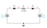
- Some participants assert that both diodes are in the "on" state, with a voltage drop of approximately 0.7 V across each diode, regardless of the current.
- One participant calculates the voltage at point A as +25 V, based on a voltage source connected between ground and point A.
- Another participant calculates the voltage at point B as 24.3 V, derived from the voltage at point A minus the diode drop (25 V - 0.7 V).
- There is uncertainty expressed about how to determine the voltage at point C, with participants seeking further clarification.
- Discussion about point D indicates there is a voltage source affecting its voltage, but details are not fully elaborated.
Areas of Agreement / Disagreement
Participants generally agree on the voltage drop across the diodes and the voltage at point A. However, there is uncertainty regarding the voltages at points C and D, and the discussion remains unresolved regarding how to calculate these values.
Contextual Notes
Participants have not fully defined the circuit configuration or the relationships between the points, leading to potential limitations in their calculations. The assumptions about the diode behavior and the voltage sources are also not explicitly stated.