Voltage theory for an LCR circuit

Join the discussion
Registration is free. Ask a follow-up in this thread, or start your own.
13 replies · 2K views
Jase
Messages
2
Reaction score
1
Thread moved from the technical forums, so no Homework Template is shown.
Summary:: I say the answer is A because these are reactive components that take and give back energy from the circuit so no voltage drop across the 2- L & C. Please let me know yours thoughts- thanks
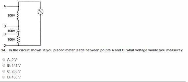
Hello I am a newby to electronics taking a class. Please review my thinking on this problem. I have a series LCR circuit with 100V given for each of the LCR components and I am ask to measure the AC voltage between points that include the L & C only. I say the answer is A because these are reactive components that take and give back energy from the circuit so no voltage drop across the 2- L & C. Please let me know yours thoughts- thanks
homework one.JPG
 
Physics news on Phys.org
Jase said:
Summary:: I say the answer is A because these are reactive components that take and give back energy from the circuit so no voltage drop across the 2- L & C. Please let me know yours thoughts- thanks

Hello I am a newby to electronics taking a class. Please review my thinking on this problem. I have a series LCR circuit with 100V given for each of the LCR components and I am ask to measure the AC voltage between points that include the L & C only. I say the answer is A because these are reactive components that take and give back energy from the circuit so no voltage drop across the 2- L & C. Please let me know yours thoughts- thanks
View attachment 261274
You need to consider the phase of the voltages you are adding. Let's assume an AC current through the network, which for the series circuit will be the same everywhere. Now can you decide the phase of the voltage developed across C and then across L relative to the phase of the current? Then you need to add these together graphically.
 
  • Like
Likes   Reactions: scottdave
Jase said:
A because these are reactive components that take and give back energy from the circuit so no voltage drop across the 2- L & C.
Not true. Their net energy over a complete cycle is zero because the current is 90 degrees out of phase with the voltage across them; not that the voltage is zero.

What do you calculate is the complex current in that loop?
 
anorlunda said:
Not true. Their net energy over a complete cycle is zero because the current is 90 degrees out of phase with the voltage across them; not that the voltage is zero.

What do you calculate is the complex current in that loop?
Hello thanks for yoru input. I will read along your lines of thought.
 
This is being made more difficult than it needs to be. Series circuit, current is the same in L, C, and R. The same voltage across all three individual components. This means that the L and C have equal and opposite reactances. In other words they form a series resonant circuit. Voltage across a series resonant circuit is zero.
 
  • Like
Likes   Reactions: Tom.G, Delta2 and NascentOxygen
Averagesupernova said:
The same voltage across all three individual components.
I don't think so
This means that the L and C have equal and opposite reactances. In other words they form a series resonant circuit. Voltage across a series resonant circuit is zero.
Voltage across the RLC series resonant circuit is obviously the excitation voltage.
 
rude man said:
I don't think so
It is given by the problem (not explicitly stated in the problem statement but it writes them in the schematic, i might interpret wrongly the schematic) that $$V_{AB}=V_{BC}=V_{CD}=100V$$
 
  • Like
Likes   Reactions: Averagesupernova
Delta2 said:
It is given by the problem (not explicitly stated in the problem statement but it writes them in the schematic, i might interpret wrongly the schematic) that $$V_{AB}=V_{BC}=V_{CD}=100V$$
Yes that's right. But the voltage across R is meaningless for answering the question which is the voltmeter reading between A and C. ## V_R = 100 ## just means that the excitation voltage is 100V.
 
Wow. Quite a misinterpretation of my post. Not sure I can state it any simpler. It's a given that all three components have the same voltage across them individually. Sure it makes no difference that we don't need to know the voltage across R but nonetheless it is there. No one argued my point about the current being the same in all three components so I guess we can assume to be in agreement there. The voltage across RLC is also given as a source voltage and I never said it was zero. To me, when picking a circuit apart as I did in my previous post a series resonant circuit is the L and the C, that's it, nothing more. Is it just me or has this been a nitpicking-fest?
 
  • Like
Likes   Reactions: Tom.G, Jody and Delta2
Averagesupernova said:
Is it just me or has this been a nitpicking-fest?
I never disagreed with anything you said once @Delta2 pointed out to me that the voltage across all 3 components was the same, a given.

Typically, that is not the case, with the voltage at resonance across L or C being several times the voltage across R.

This and other circuits (L-R, R-C) have what is called "Q". In your circuit, Q = ## \omega L/R = 1/(\omega RC) ## and in general is the ratio of max. energy .stored/energy dissipated in 1 cycle.

So the voltage across L or C is Q times the voltage across R. Your circuit has a very low Q of 1. Typical radio tuned circuit Q might be 15. A quartz crystal can have Q in the 1000's which is why they're used where accurate resonant frequency generation is critical.
 
Q is meaningless for answering the question the same way the voltage across R is meaningless. My point stands. You were wrong and it's big of you to admit that @Delta2 straightened you out. I suspected when all three voltages in this problem were the same as the supply voltage that it was a problem designed to be solved without picking up a pencil. If the student knows their stuff, they will answer without the need to show any more of their work than I did in my first post.
 
Well, @rude man made a mistake in reading the problem's data, which he admitted so all good.

However I think he made a successful comment, by saying that the voltage across the series RLC resonant circuit equals the excitation voltage, that is the voltage across the ohmic resistance of the circuit. Resonant circuits have to have some ohmic resistance as well, because if we have a resonant circuit consisting of LC only and we have it connected it to an ideal (of zero internal impedance) voltage source, then the current will be infinite and the voltage across the resonant circuit will not be zero but will equal the source voltage.